Oscillation circuit

a technology of oscillating circuit and oscillating frequency, which is applied in the direction of pulse generator, pulse technique, electrical apparatus, etc., can solve the problems of difficult in practice to eliminate the temperature dependency of resistor r, oscillation frequency fluctuation, and oscillation frequency fluctuation, so as to reduce the temperature dependency of oscillation frequency and constant oscillation frequency , the effect of high resistance of the first variable resistor

Inactive Publication Date: 2012-12-20
LAPIS SEMICON CO LTD
View PDF6 Cites 12 Cited by
  • Summary
  • Abstract
  • Description
  • Claims
  • Application Information

AI Technical Summary

Benefits of technology

[0012]In consideration of the above circumstances an object of the present invention is to provide an oscillation circuit that can reduce the temperature dependency of the oscillation frequency to enable high-precision oscillation when high-precision oscillation is required, and that can also reduce current consumption of the integrated circuit when high-precision oscillation is not required.
[0017]In the oscillation circuit of the present invention, the voltage-current conversion circuit converts the output voltage output from the band-gap circuit to an output current according to the resistance of the first variable resistor, and outputs a bias voltage based on the converted output current to the comparator section of the CR oscillation circuit. Temperature dependency is adjusted in stages by the band-gap circuit and the voltage-current conversion circuit, thereby enabling the temperature dependency of the oscillation frequency to be reduced and a constant oscillation frequency to be achieved irrespective of temperature.
[0018]The voltage-current conversion circuit also converts to an output current according to the resistance of the first variable resistor. Therefore the resistance of the first variable resistor can be set high to reduce the temperature dependency of the oscillation frequency when high-precision oscillation is required, such as during CPU operation. The resistance of the first variable resistor can also be set low to reduce current consumption when high-precision oscillation is not required, such as when in standby or halt modes.
[0019]According to the present invention, the advantageous effect is exhibited of providing an oscillation circuit that can reduce the temperature dependency of the oscillation frequency to enable high-precision oscillation when high-precision oscillation is required, and that can also reduce current consumption when high-precision oscillation is not required.

Problems solved by technology

However, the resistance of a resistor R is temperature dependent and fluctuates according to temperature, resulting in the issue that the oscillation frequency also fluctuates according to temperature (namely the oscillation frequency is also temperature dependent).
It is accordingly difficult in practice to eliminate the temperature dependency of the resistor R. It is also known that the oscillation frequency fluctuates according to temperature due to factors such as the temperature dependency of internal resistance of elements other than the resistor R (the capacitors C, inverter and comparator) and temperature dependency of parasitic resistance.
However, when trimming is performed using two types of resistor, the scale of the circuit increases, and an additional mask is required for resistor fabrication, leading to new issues arising, such as an increase in integrated circuit fabrication cost.
Due to the resistance of the externally attached resistor being fixed at the design stage, the temperature dependency of the reference resistor cannot be adjusted, resulting in the issue that it is ultimately difficult to adjust the temperature dependency of the oscillation frequency.
The oscillation circuit described in JP-A No. 2008-252414 also employs the method of controlling the amperage flowing from the invertor into the capacitor, and so there is the issue that it is difficult to achieve both low consumption and to reduce the temperature dependency when required.
It is accordingly difficult to reduce the temperature dependency of the oscillation frequency during CPU operation when high-precision oscillation is required, and to also reduce current consumption of the oscillation circuit when in standby or halt modes when high-precision oscillation is not required.

Method used


Image

  • Oscillation circuit
  • Oscillation circuit
  • Oscillation circuit

Examples


Embodiment Construction

[0030]Explanation follows regarding an exemplary embodiment of the present invention, with reference to the drawings.

[0031]CR Oscillation Circuit Configuration

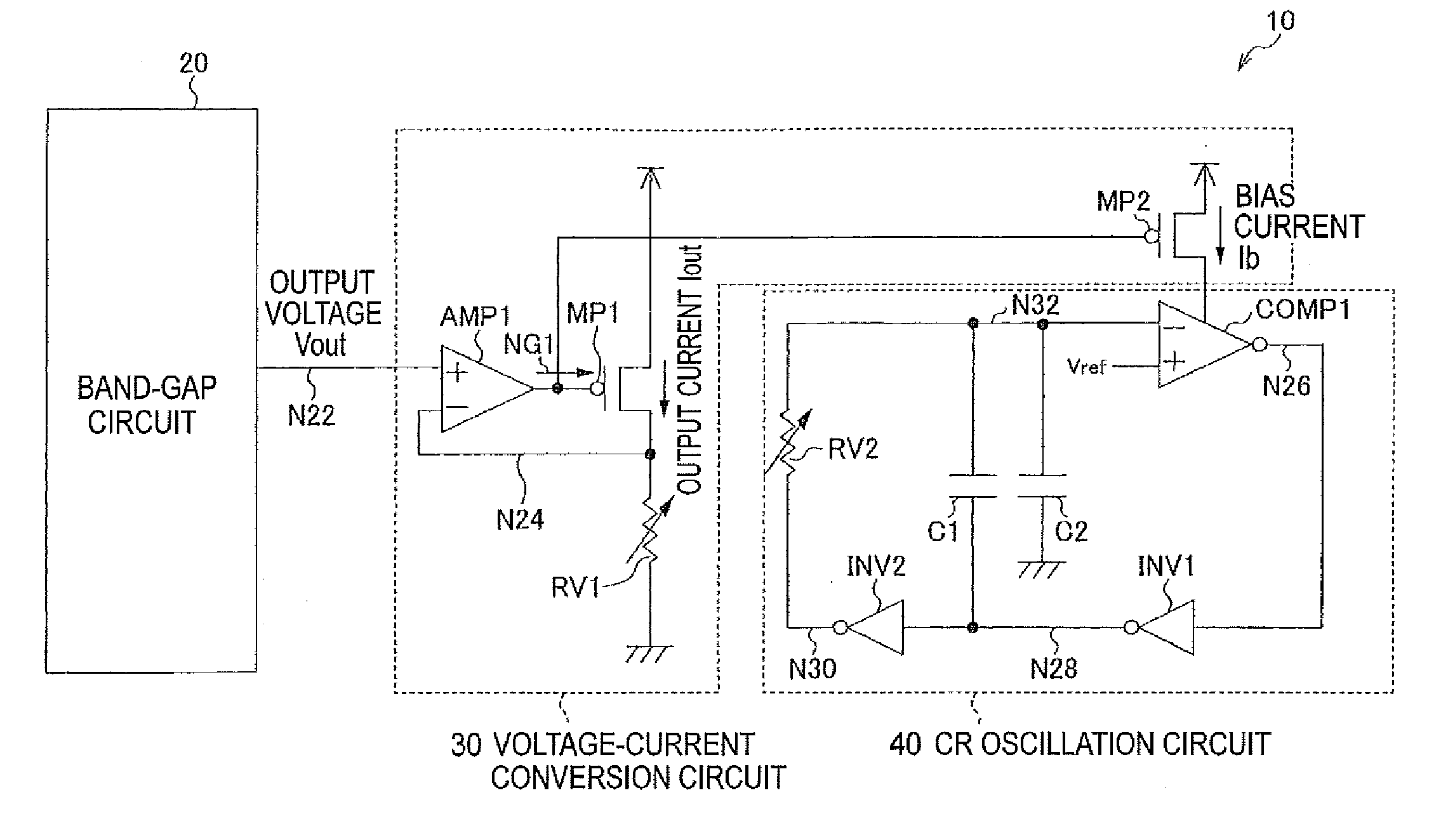
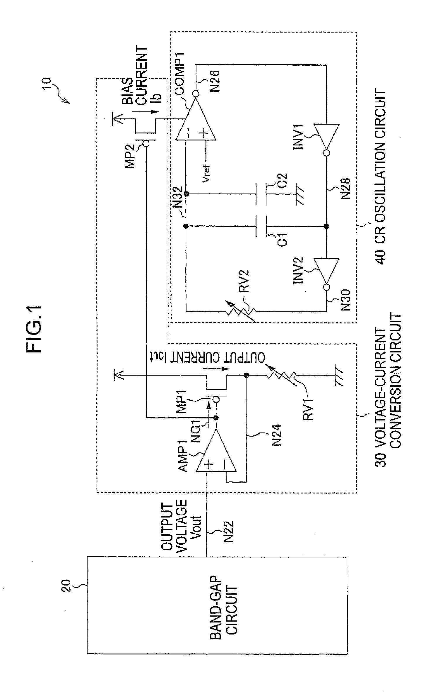
[0032]FIG. 1 is a circuit diagram illustrating an example of a configuration of an oscillation circuit according to an exemplary embodiment of the present invention. An oscillation circuit 10 is mounted on an integrated circuit, such as a CPU of a microcomputer. As shown in FIG. 1, the oscillation circuit 10 includes a band-gap circuit 20 that outputs an output voltage Vout adjusted for temperature dependency, a voltage-current conversion circuit 30 that converts the output voltage Vout of the band-gap circuit 20 to an output current Iout and outputs a bias current Ib based on the output current Tout, and a CR oscillation circuit 40 that operates according to a bias current Ib input from the voltage-current conversion circuit 30.

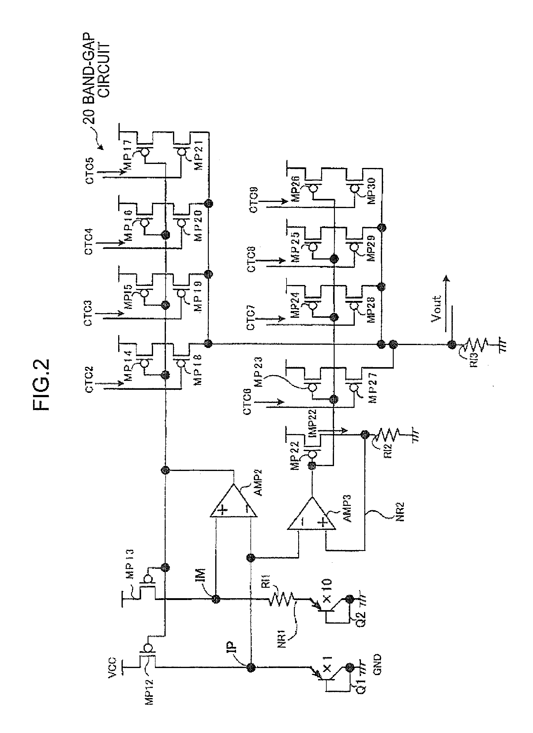
[0033]Generally, a band-gap circuit is a circuit for obtaining an output voltage Vout independent o...


PUM


Abstract

There is provided an oscillation circuit including: a band-gap circuit that outputs an output voltage adjusted for temperature dependency so as to give a constant output voltage independent of temperature; a voltage-current conversion circuit including a first variable resistor, the voltage-current conversion circuit converting an output voltage output from the band-gap circuit into an output current corresponding to the resistance of the first variable resistor and outputting a bias current based on the converted output current; and a CR oscillation circuit including a second variable resistor, a capacitor and a comparator section, the CR oscillation circuit oscillating with an oscillation frequency based on the resistance of the second variable resistor and the capacitance value of the capacitor, and the CR oscillation circuit operating according to the amperage of the bias current the comparator section has input from the voltage-current conversion circuit.

Description

CROSS-REFERENCE TO RELATED APPLICATION[0001]This application is based on and claims priority under 35 USC 119 from Japanese Patent Application No. 2011-132544 filed on Jun. 14, 2011, the disclosure of which is incorporated by reference herein.BACKGROUND[0002]1. Technical Field[0003]The present invention relates to an oscillation circuit and in particular to an oscillation circuit capable of high-precision oscillation.[0004]2. Related Art[0005]Conventionally comparatively cheap high-precision CR (capacitor resistor) oscillation circuits are employed in place of high cost quartz oscillation circuits as oscillation circuits mounted on integrated circuits such as in Central Processing Units (CPUs) of microcomputers. CR oscillation circuits are configured, for example as shown in FIG. 7, with a resistor R3, a capacitor C1, a capacitor C2, a comparator 4, an inverter 5 and an inverter 6. The oscillation frequency of a CR oscillation circuit is determined by the values of the resistor R an...

Claims


Application Information

Patent Timeline
Patent Type & Authority Applications(United States)
IPC IPC(8): H03L1/00
CPCH03K3/0231H03K3/011
Inventor IWASA, YOSUKE
Owner LAPIS SEMICON CO LTD
Why Eureka
Try Eureka