Liquid crystal display device, and LED backlight unit

a technology of led backlight and display device, which is applied in the direction of illuminated signs, display means, instruments, etc., can solve the problems of reducing the luminous efficiency and the longevity of leds, and achieving the effects of easy formation, increased thickness, and large cross-sectional area

Inactive Publication Date: 2012-12-20
SHARP KK
View PDF10 Cites 45 Cited by
  • Summary
  • Abstract
  • Description
  • Claims
  • Application Information

AI Technical Summary

Benefits of technology

[0026]The configuration of the liquid crystal display device and the LED backlight unit of the preferred embodiments of the present invention that the cooling air that defines a cooling medium runs through the through flow path including the main duct arranged to introduce the cooling air and the branch duct aligned along the disposed direction of the LED light source allows the heat generated by the emission of light from the LED light source to be cooled efficiently. In addition, the configuration that the branch duct includes the exhaust port disposed at the end of the branch duct allows the air used for cooling to be discharged to the outside of the device. In other words, the cooling air that has risen in temperature can be discharged to the outside to introduce new cooling air (low in temperature) in turn into the main duct. Thus, it is unnecessary to provide a cooling-medium cooling mechanism such as a cooler arranged to cool the cooling air that has risen in temperature.
[0027]When the LED light source is the “direct” backlight having the configuration that the LED light source is disposed over the entire surface of the chassis plate that is opposed to the liquid crystal display panel, the branch ducts are aligned along the LED light source on the entire surface. Meanwhile, when the LED light source is the“side” backlight having the configuration that the LED light sources are disposed on the opposed inner surfaces of the chassis plate, the main duct and the branch duct are aligned along the inner surfaces. These configurations of the through flow path disposed in accordance with the disposition of the light source(s) allow the LED light source(s) to be cooled efficiently.
[0028]The configuration that each flow passage of the plurality of branch ducts has the rectangular shape in cross section can prevent the branch ducts from increasing in thickness while allowing a flow rate of the cooling air for cooling the LED light source to be increased (allowing a large cross-sectional area to be obtained). The configuration that each flow passage of the plurality of branch ducts has the round shape in cross section allows the flow passages to be easily formed. The configuration that each flow passage of the plurality of branch ducts has the triangular shape in cross section and the follow passages face and fit each other can prevent the branch ducts from increasing in thickness while allowing a flow rate of the cooling air for cooling the LED light source to be increased (allowing a large cross-sectional area to be obtained).
[0029]The configuration that the cooling air flows upward allows the air (air used for cooling) that has been heated by the light source to be discharged smoothly to the outside of the device.
[0030]The configuration that the exhaust port disposed at the end of the branch duct is open toward the back surface of the device can reduce an adverse effect caused by the discharge air used for cooling. To be specific, because the liquid crystal display device is usually installed such that its back surface is opposed to a wall of a house, the configuration that the air is discharged from the back surface of the device improve the usability of the display device.
[0031]The configuration that the through flow path and the chassis plate are of separate construction allows the through flow path to be easily formed. Meanwhile, the configuration that the through flow path and the chassis plate are of monolithic construction can improve the cooling effect of the LED light source because the cooling air runs closer to the LED light source.

Problems solved by technology

However, the cold cathode fluorescent lights contain mercury that is a harmful material in their discharge tubes, so that there arises an environmental problem such as a problem of disposal of the used tubes.
However, because LED tips of the LED light source generate heat, the LED light source has a problem of reduction in luminous efficiency and reduction in longevity of the LEDs.
For example, if the amounts of the current to the LEDs are increased to increase the brightness of each LED, the heating values from the LEDs rise, which reduces the luminous efficiency and the longevity of the LEDs.

Method used


Image

  • Liquid crystal display device, and LED backlight unit
  • Liquid crystal display device, and LED backlight unit
  • Liquid crystal display device, and LED backlight unit

Examples


first embodiment

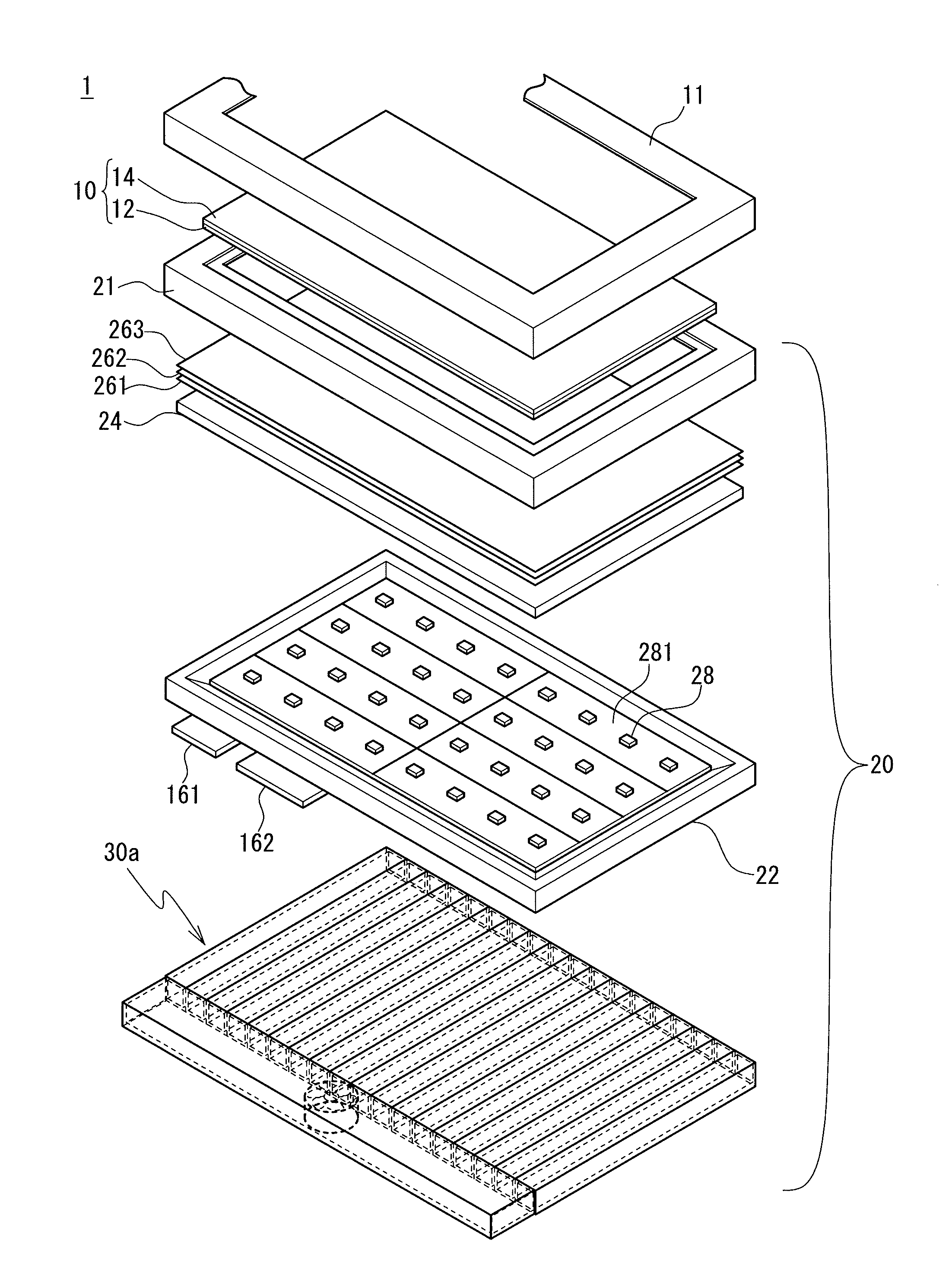
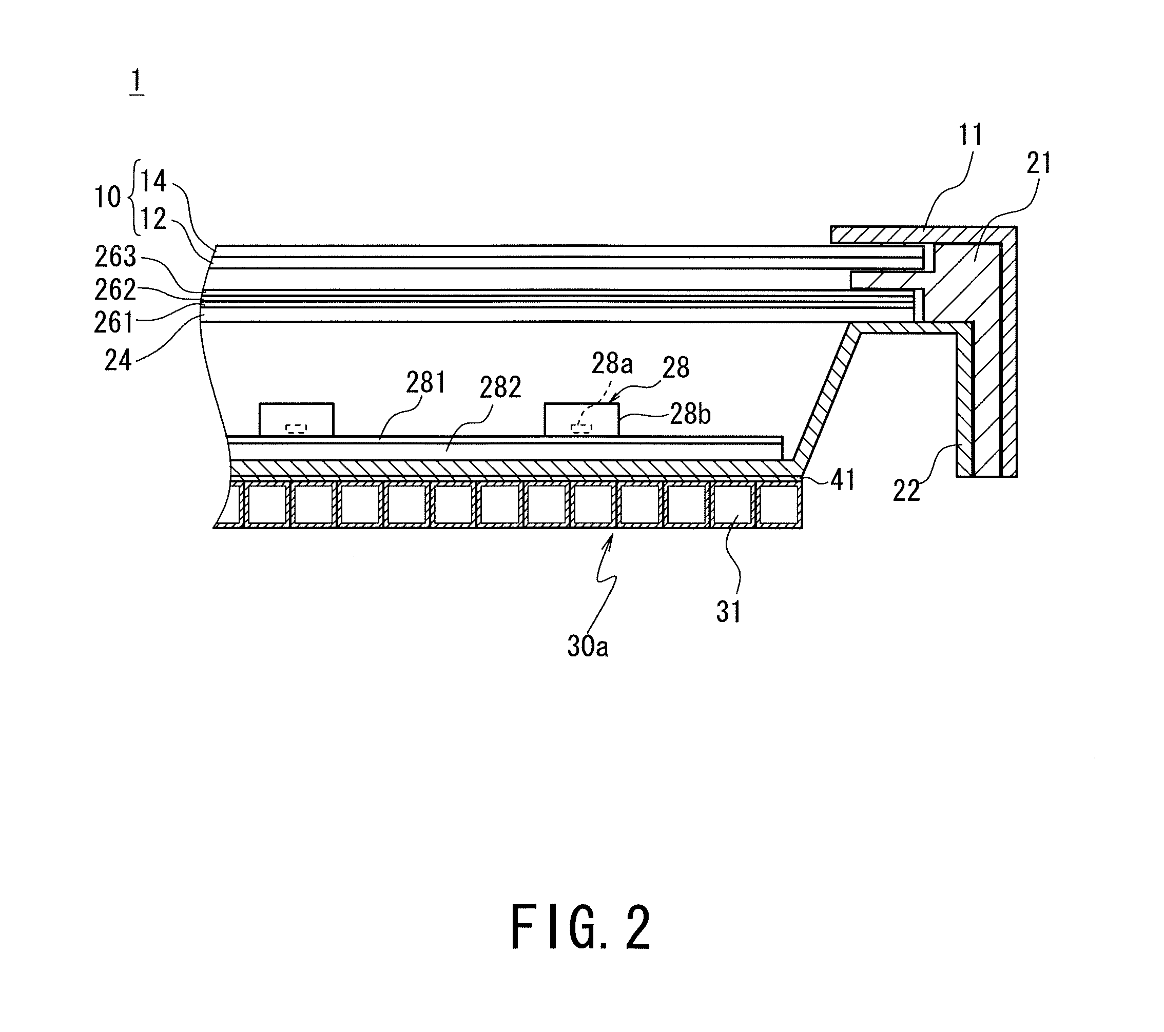
[0052]The LED backlight unit 20 (the LED backlight unit of the first embodiment) defines an illuminating device that is used disposed behind the liquid crystal display panel 10. The LED backlight unit 20 of the present embodiment defines a so-called “direct” LED backlight unit having a configuration such that LED light sources 28 are disposed over the entire surface of the LED backlight unit 20, the surface being opposed to the liquid crystal display panel 10.

[0053]The LED backlight unit 20 includes a frame 21, a chassis plate 22, a diffusion plate 24, optical sheets 261, 262 and 263, the LED light sources 28, and a cooling device 30a as shown in FIGS. 1 and 2.

[0054]The frame 21 has a square frame shape, where sides which form the frame have the shape of the letter “L” in cross section. The frame 21 is arranged to fix the diffusion plate 24 and the optical sheets 261, 262 and 263 that are stacked on the chassis plate 22. To be specific, edge portions of the diffusion plate 24 and th...

second embodiment

[0077]In the liquid crystal display device of the second embodiment, the cooling air that has risen in temperature can be discharged to the outside of the device from the exhaust port 323a of the exhaust duct 323 to introduce new cooling air (low in temperature) in turn into the main duct 321. Thus, it is unnecessary to provide a cooling-medium cooling mechanism such as a cooler arranged to cool the cooling air that has risen in temperature.

[0078]Further, the exhaust duct 323 connected to the top ends of the first branch ducts 322 is provided, and the exhaust port 323a is provided to the exhaust duct 323 in the present embodiment. To be specific, the display device of the present embodiment has the configuration that the air that runs through the first branch ducts 322 and used for cooling is collected at the exhaust duct 323 and discharged from the exhaust port 323a. Thus, the area of the exhaust of the discharged air can be decreased. In addition, changing the position of the exha...

third embodiment

[0084]In the liquid crystal display device of the third embodiment, the cooling air that has risen in temperature can be discharged to the outside of the device from the exhaust port 332a of the branch duct 332 to introduce new cooling air (low in temperature) in turn into the main duct 331. Thus, it is unnecessary to provide a cooling-medium cooling mechanism such as a cooler arranged to cool the cooling air that has risen in temperature.

[0085]Further, in the present embodiment, the branch duct 332 is winding so as to run in a zigzag in the up / down direction and thus has a flat plate shape in order to cool the “direct” backlight that is made up of the LED light sources 28 disposed in a planar fashion. This configuration allows the area of the exhaust of the discharged air to be decreased, and allows the air heated by the LED light sources 28 to be smoothly discharged to the outside of the device.

[0086]A liquid crystal display device (an LED backlight unit) of a fourth embodiment of...


PUM

PropertyMeasurementUnit
thicknessaaaaaaaaaa
shapeaaaaaaaaaa
brightness distributionaaaaaaaaaa

Abstract

Provided is a liquid crystal display device and a backlight unit that are of high quality and have a simple configuration that a mechanism cooling a cooling medium is not included. Included are a liquid crystal display panel and an LED backlight unit including an LED light source emitting light toward the panel, and a chassis plate on which the light source is disposed, the plate including a through flow path for cooling air dissipating heat from the light source, wherein the path includes a main duct introducing the cooling air and disposed along one side of the panel, and a branch duct branching off from the main duct, aligned along a disposed direction of the light source, and including an exhaust port disposed at an end of the branch duct and discharging the cooling air to outside of the device.

Description

TECHNICAL FIELD[0001]The present invention relates to an LED backlight unit including LEDs that define a light source, and having a configuration of dissipating heat that is generated by emission of light from the LED light source, and relates to a liquid crystal display device including the LED backlight unit of this kind.BACKGROUND ART[0002]A liquid crystal display device including a transmissive liquid crystal display panel includes a backlight unit arranged to project light onto the liquid crystal display panel. The backlight unit of this kind generally includes a light source, and an optical member such as a diffusion sheet that is arranged to uniform brightness distribution of the light emitted from the light source.[0003]Recently, compact fluorescent tubes that are referred to as cold cathode fluorescent lights (CCFLs) are often used as a light source in a liquid crystal display device. However, the cold cathode fluorescent lights contain mercury that is a harmful material in...

Claims


Application Information

Patent Timeline
Patent Type & Authority Applications(United States)
IPC IPC(8): G02F1/13357F21V29/02
CPCG02F1/133603G02F2001/133628G02F2201/36G02F1/133628
Inventor NAMEKATA, YUUKI
Owner SHARP KK
Why Eureka
Try Eureka