
Channel estimation for OFDM systems

a channel estimation and channel estimation technology, applied in the field of orthogonal frequency division modulation (ofdm) communication systems, can solve the problems of high computational cost, high computational cost, and the inability to accurately estimate the channel fading of signals received from ofdm transmitting antennas, so as to reduce complexity and improve method performance.

Inactive Publication Date: 2012-12-20
LENOVO INNOVATIONS LTD HONG KONG
View PDF2 Cites 11 Cited by
  • Summary
  • Abstract
  • Description
  • Claims
  • Application Information

AI Technical Summary

Benefits of technology

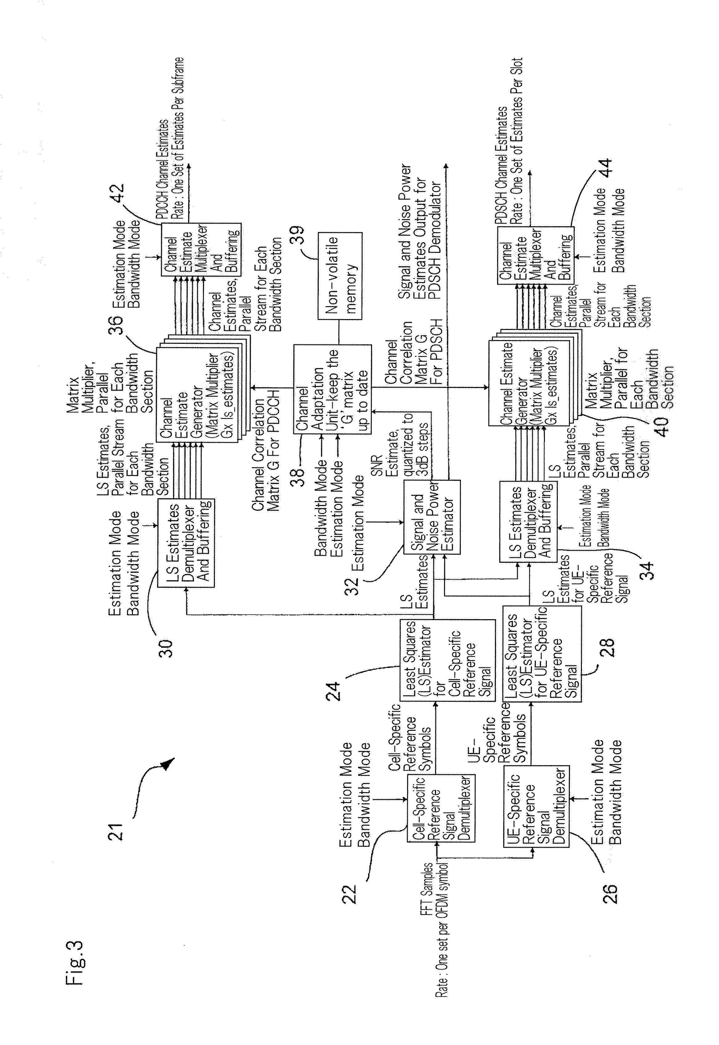
[0031]The method reduces the complexity of the channel estimator because Doppler spread and delay spread values do not need to be estimated and updated at the time of performing the channel estimation. Instead, for each signal to noise ratio a single matrix G is precalculated that covers all range of realistic values for Doppler frequency and delay spread. This increases robustness (against channel conditions) and reduces complexity of the channel estimator. The Doppler frequency and delay spread values may be chosen and fixed so that the estimation is robust to different channels within the normal test conditions for e.g. a LTE / LTE-A UE.
[0062]The device may further include a LS estimator for calculating the LS estimates from the reference signal. The device may then internally calculate Least Squares estimates, which are in turn used for multiple purposes. For example, in the case when the device is used within a UE, the LS estimates may be used for channel estimation for the data channel (PDSCH), channel estimation for the control channel (PDCCH) and Signal-to-Noise ratio estimation. In some prior art designs, each of these required a separate LS estimator, resulting in larger complexity.

Problems solved by technology

Signals received from OFDM transmitting antennas may be subject to channel fading due to multipath propagation or interference between the signals and geographical surroundings.
Equation 2-1 shows how the channel estimator 18 calculates the G matrix from the component matrices A and B. Since large matrix inversion is required, this operation is computationally intensive.
The calculation of the Bessel function for each element of the matrices is also computationally intensive.
These complexities limit the use of 2D LMMSE channel estimation in commercial products.

Method used


Image

  • Channel estimation for OFDM systems
  • Channel estimation for OFDM systems
  • Channel estimation for OFDM systems

Examples


Embodiment Construction

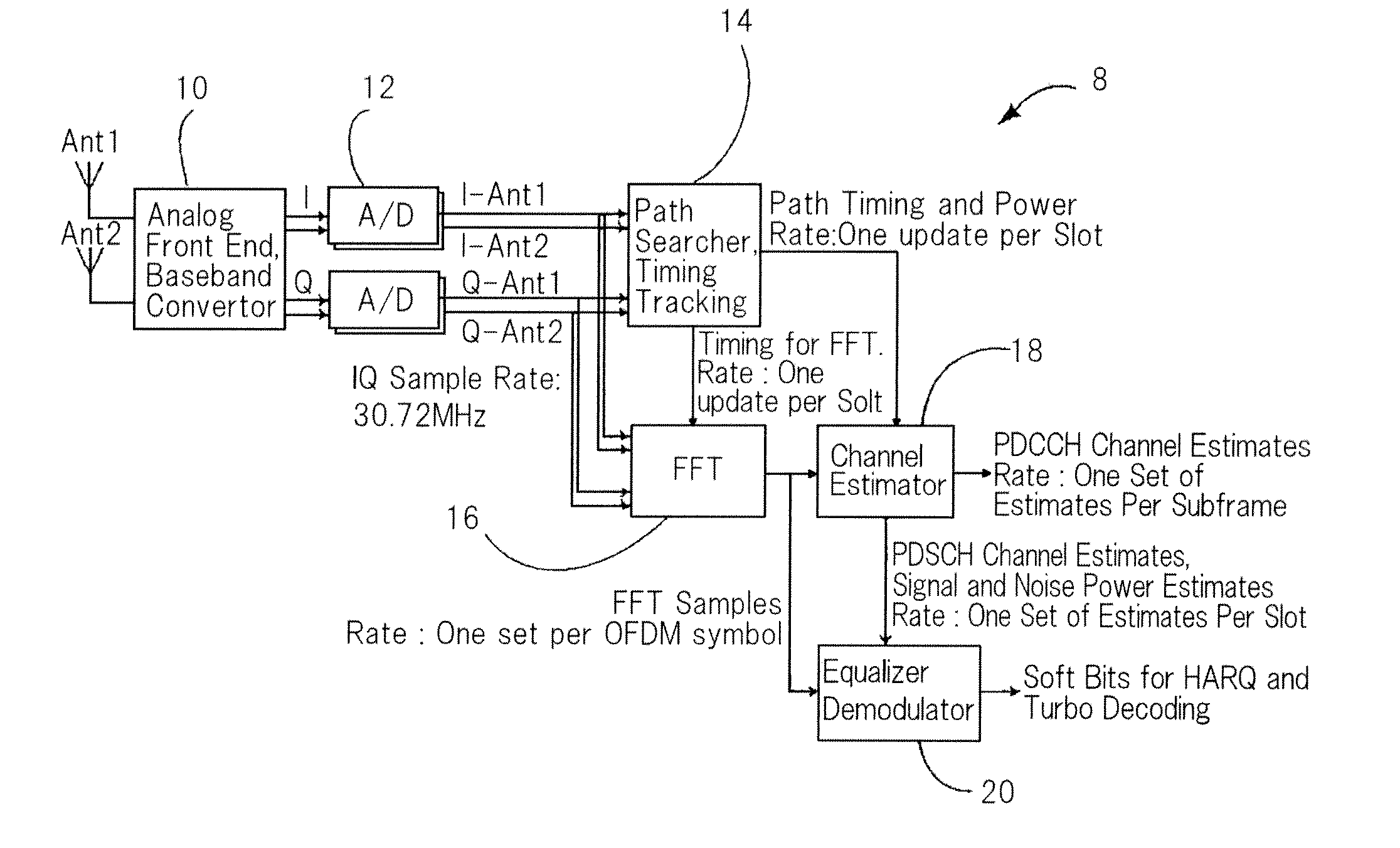
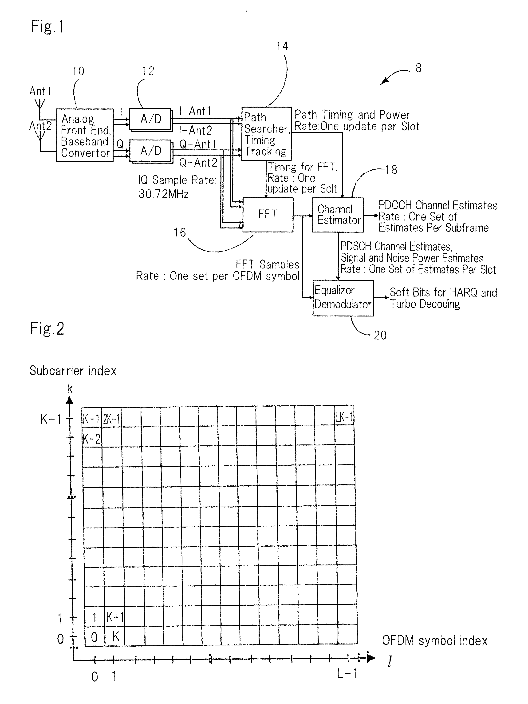
[0070]An embodiment of the invention will be described with reference to channel estimation in an LTE / LTE-A UE receiver 8, as shown in FIG. 1. It is understood that the invention is not limited to this embodiment and is applicable in the BTS, as well as other OFDM based systems.

[0071]With reference to FIG. 4, the following steps are performed during device design time, to build a look up table containing a set of G matrices for use in channel estimation. For each mode in a range of all valid processing modes, a G matrix is precalculated at step 50 for each SNR in a range of SNR values using a fixed Doppler frequency and a fixed delay spread. At step 52, the G matrices are indexed by the signal to noise ratio and processing mode. However, it is to be understood that the G matrices may be precalculated only for a single processing mode, and may be indexed by SNR only. A specific example of the method is described below: For a plurality of discrete signal to noise ratios (such as a ran...


PUM


Abstract

A device for performing channel estimation in an OFDM system includes a non-volatile memory, a G matrix selector and a channel estimate generator. The non-volatile memory stores a set of G matrices indexed by signal to noise ratio, the G matrices being precalculated for a plurality of signal to noise ratios using a fixed Doppler frequency and a fixed delay spread. The G matrix selector uses a quantised signal to noise ratio to select a G matrix from the set of G matrices stored in the non-volatile memory. The channel estimate generator multiplies the selected G matrix by LS estimates for the reference signal to obtain a channel estimation.

Description

TECHNICAL FIELD[0001]The present invention relates generally to orthogonal frequency division modulation (OFDM) communication systems, and in particular to improvements in channel estimation for an OFDM system.BACKGROUND[0002]OFDM is a digital multi-carrier modulation method that uses a large number of closely spaced orthogonal sub-carriers to carry data. OFDM is becoming widely applied in wireless communication systems due to the high rate transmission capability with high bandwidth efficiency. Signals received from OFDM transmitting antennas may be subject to channel fading due to multipath propagation or interference between the signals and geographical surroundings. To take account of this, reference signals are mapped onto subcarriers and used at the receiver to obtain channel estimations.[0003]FIG. 1 shows a user equipment (UE) receiver 8 for an OFDM system, which transforms a received radio frequency signal into soft bits representing data. An analog front end 10 amplifies an...

Claims


Application Information

Patent Timeline
Patent Type & Authority Applications(United States)
IPC IPC(8): H04B15/00H04B17/00
CPCH04J11/0036H04L25/0204H04L25/022H04L25/0222H04L25/0242H04L27/2647
Inventor PHAM, DUONGZALIO, FILIP
Owner LENOVO INNOVATIONS LTD HONG KONG
Learn More