
Compound Sealing Method for Vacuum Glass

Active Publication Date: 2012-12-20
LUOYANG LANDGLASS TECH CO LTD
View PDF12 Cites 56 Cited by
  • Summary
  • Abstract
  • Description
  • Claims
  • Application Information

AI Technical Summary

Benefits of technology

[0014]Further, the metal material contained in the metal paste has favorable brazing performance.
[0035]The invention realizes the air-tight joint between glass plates by adopting the metal brazing technology, and thus provides a brand new technological method for the compound sealing between glass plates. This method has the advantages of firm connection in sealing positions, high air tightness, favorable thermal shock resistance and the like, and avoids the annealing of toughened glass because of a lower brazing temperature to be used, thereby providing convenience to the processing of toughened vacuum glass, toughened insulated glass and other toughened compound glass products. In addition to the use for the processing of vacuum glass, insulated glass and other glass products, the compound sealing method of the invention can also be used for the connection between glass plates, and the metal paste type and the brazing mode can be chosen flexibly according to the actual demands, conditions and types of processed products, thereby enabling the method of the invention to achieve the characteristics of high applicability and wider application field.

Problems solved by technology

(1) Use fits with a low melting point to be melted for sealing, wherein the sealing temperature is 400-500° C. or so in general, and by means of flame or electrical heating, the fits with the low melting point are melted so as to complete the compound sealing between the glass plates. The glass with the low melting point used by the process is usually PbO—ZnO sealing glass, and such material is hardly conducive to environmental protection requirements for its future development since lead is harmful to the environment and human bodies. Meanwhile, equipment and processes for manufacturing the material are complicated, and the glass plates after compound sealing also can generate boundary heat stress frequently, thereby needing an additional proper annealing treatment which greatly lowers the production efficiency. In addition, if this process is adopted to seal toughened glass, the glass will lose its safety properties due to glass annealing.
(2) Adopt various plastic or resin materials to carry out the compound sealing between the glass plates. Some patent documents mention that organic glasses such as PC, ABS, LDPE, PVC and the like are used, laminated glass materials such as PVB, EVA (EN) and the like are used in some patent documents, and processing methods are both as follows: place the above materials between two glass plates to be made into prefabricated parts, and then press the prefabricated parts under appropriate conditions. Such process is similar to the process for manufacturing laminated glasses, and can realize the compound sealing between glass plates. However, it is difficult to guarantee the leak tightness at the joints because the gas permeability and moisture permeability of majorities of the plastic and resin materials are far greater than those of glasses and majorities of the organic materials are only physically bonded with surfaces of the glass plates; and decrease in sealing strength, interlayer dewing and mildewing of glass will be directly caused in case of permeation of gases (including water vapor). In addition, the aging of the organic material will have a direct influence on the sealing effect and life of the compounded glass plates as time goes on.
(3) In order to eliminate the annealing problem in the process of sealing the toughened glasses, many patent documents mention a method of section-compartmentalized heating, i.e. locally heating the sealing position by means of microwave, high frequency, infrared ray, laser or the like to directly melt edges of two or more glass plates together under the condition of keeping a low temperature of the glass plate bodies; and some documents mention a photosensitive curing method is used to carry out the compound sealing between the glass plates. However, these methods are still in the contemplation or lab stage, and no such mature technology or products have been brought to the market. Besides, the aging of the bonding material remains even though an optical light-sensitive is used for the compound sealing between the glass plates.

Method used


Image

  • Compound Sealing Method for Vacuum Glass
  • Compound Sealing Method for Vacuum Glass
  • Compound Sealing Method for Vacuum Glass

Examples


Embodiment Construction

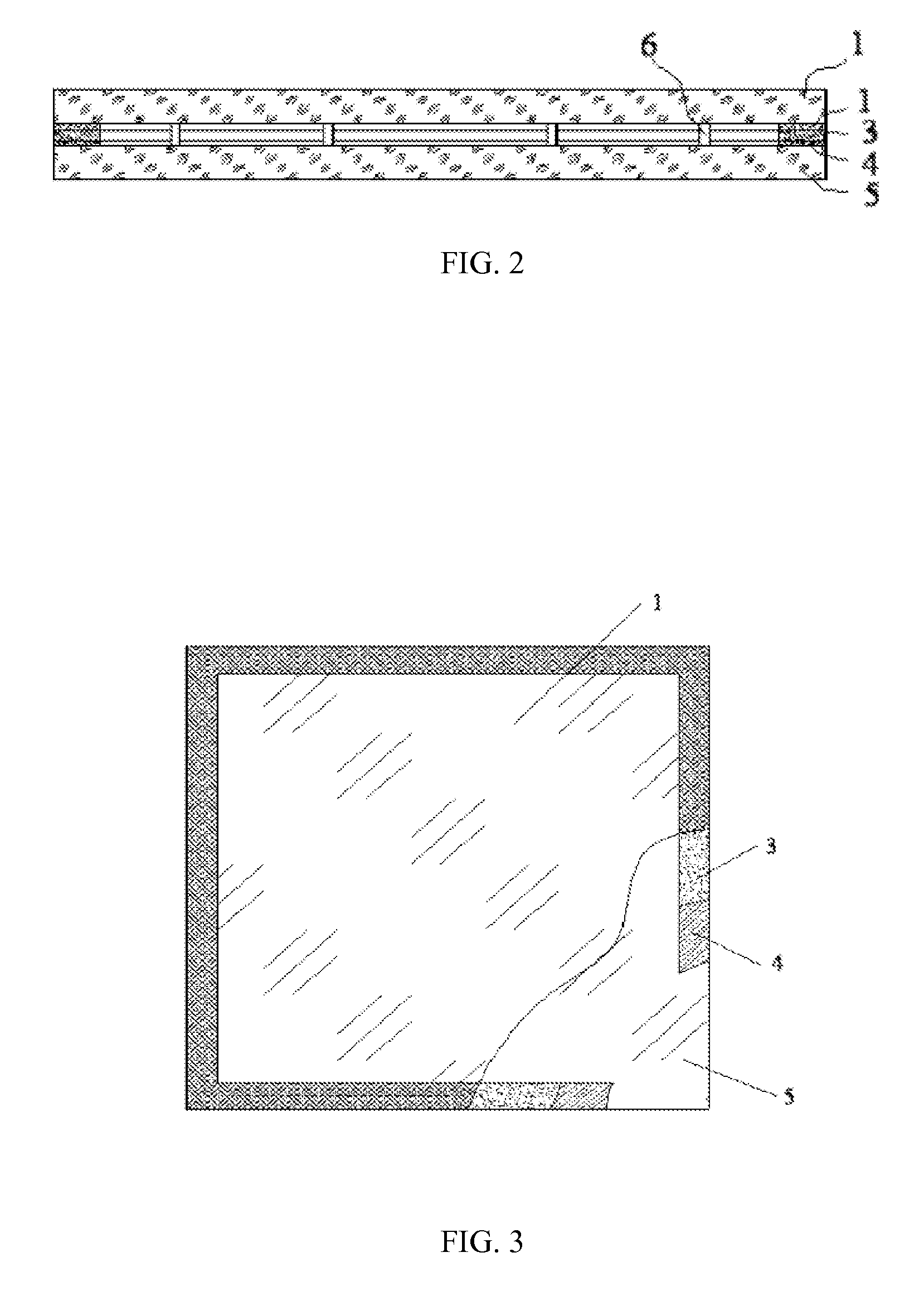
[0041]Sectional views of two-layer compound glass structure manufactured are shown in FIG. 2 and FIG. 3 according to the compound sealing method of the invention, a sectional view of a three-layer compound glass structure shown in FIG. 4, a sectional view of a toughened insulated glass structure is shown in FIG. 5, and numbers in the drawings respectively represent the following items: 1 for upper glass plate, 4 for metalized layer formed after sintering treatment of glass plate, 3 for brazing filler, 5 for lower glass plate, 2 for intermediate glass plate, 6 for intermediate support and 7 for metal spacer.

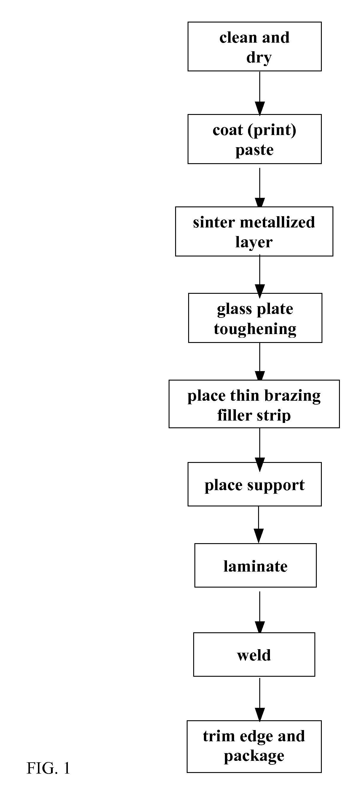
[0042]FIG. 1 shows the main technological process for the compound sealing of toughened glass plates by the compound sealing method of the invention, and this technological process will be explained below based on the two-layer compound glass in FIG. 2:

[0043]1) Cut two glass plates based on dimension requirements, and complete their edging, and washing away their grease contaminat...


PUM

PropertyMeasurementUnit
Temperatureaaaaaaaaaa
Electrical resistanceaaaaaaaaaa

Abstract

The invention relates to a compound sealing method for glass plates, which is characterized by realizing the air-tight joint between compounded glass plates in a preset position by using a metal brazing technology. The invention provides a brand new technological method for the compound sealing between glass plates. The method has the advantages of firm connection in sealing positions, high air tightness, favorable thermal shock resistance and the like, and the annealing of toughened glass are avoided because of a lower brazing temperature used, thereby providing convenience to the processing of toughened vacuum glass, toughened insulated glass and other toughened compound glass products

Description

TECHNICAL FIELD [0001]The present invention relates to a compound sealing method for glass plates, in particular, relates to a method for realizing the air-tight joint between compounded glass plates with each other in a preset position by using a metal brazing technology.BACKGROUND ART [0002]Generally, the existing compound sealing methods for glass plates are as follows:[0003](1) Use fits with a low melting point to be melted for sealing, wherein the sealing temperature is 400-500° C. or so in general, and by means of flame or electrical heating, the fits with the low melting point are melted so as to complete the compound sealing between the glass plates. The glass with the low melting point used by the process is usually PbO—ZnO sealing glass, and such material is hardly conducive to environmental protection requirements for its future development since lead is harmful to the environment and human bodies. Meanwhile, equipment and processes for manufacturing the material are comp...

Claims


Application Information

Patent Timeline
IPC IPC(8): B23K1/19B23K1/20E06B3/677
CPCB23K1/0008C03C27/08E06B3/66304E06B3/66357E06B3/67334E06B3/67326Y10T428/215Y10T428/24331Y02A30/249Y02B80/22E06B3/66C03C17/06
Inventor LI, YANBING
Owner LUOYANG LANDGLASS TECH CO LTD
Learn More