
Protective enclosure

a protective enclosure and enclosure technology, applied in the direction of soldering apparatus, manufacturing tools,auxillary welding devices, etc., can solve the problems of difficult monitoring or visualizing the welding process, risky welding process and care, and robots often working autonomously, so as to reduce mobility, enhance quality video, and convenient mounting

Inactive Publication Date: 2012-12-27
DEERE & CO
View PDF8 Cites 23 Cited by
  • Summary
  • Abstract
  • Description
  • Claims
  • Application Information

AI Technical Summary

Benefits of technology

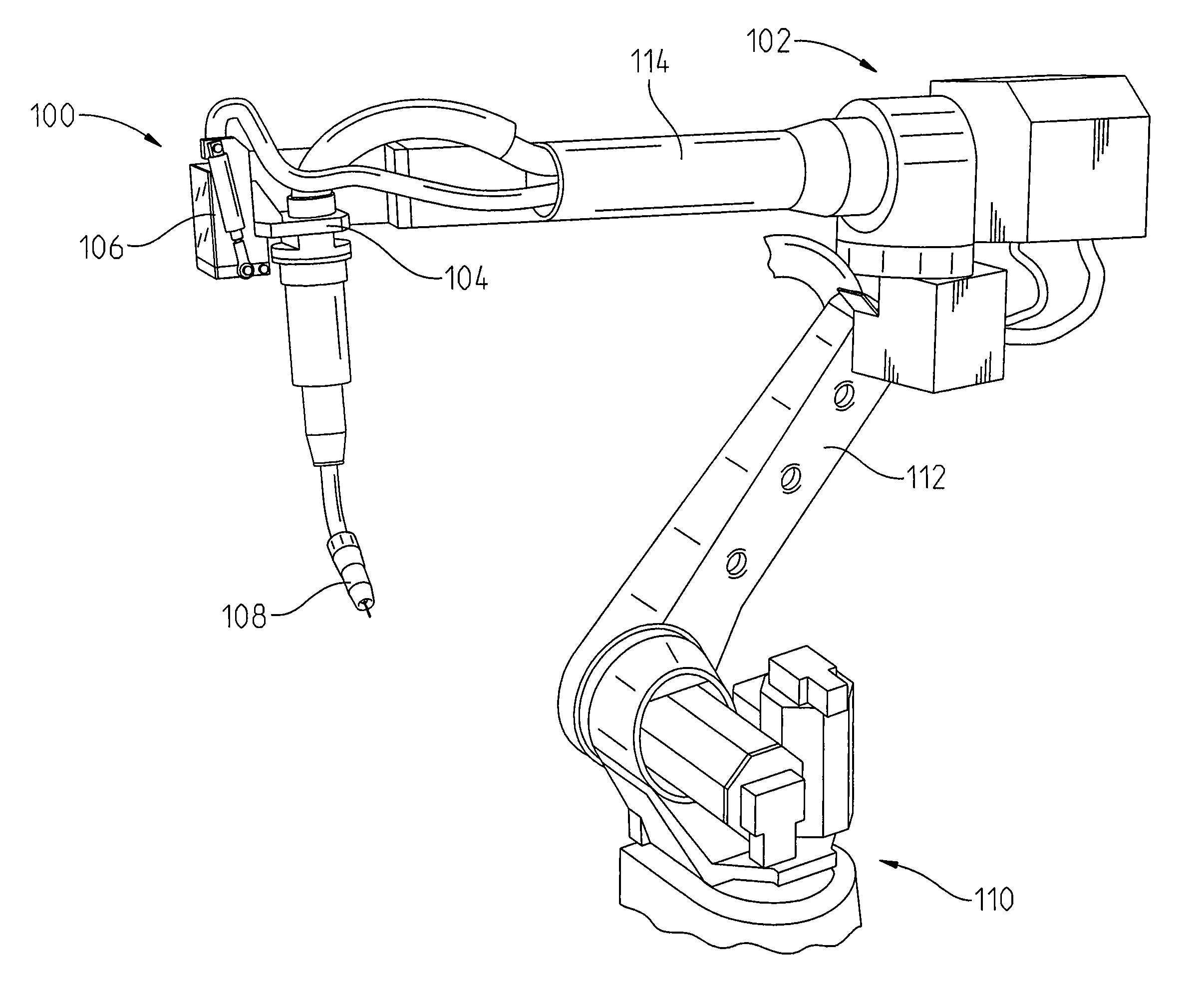
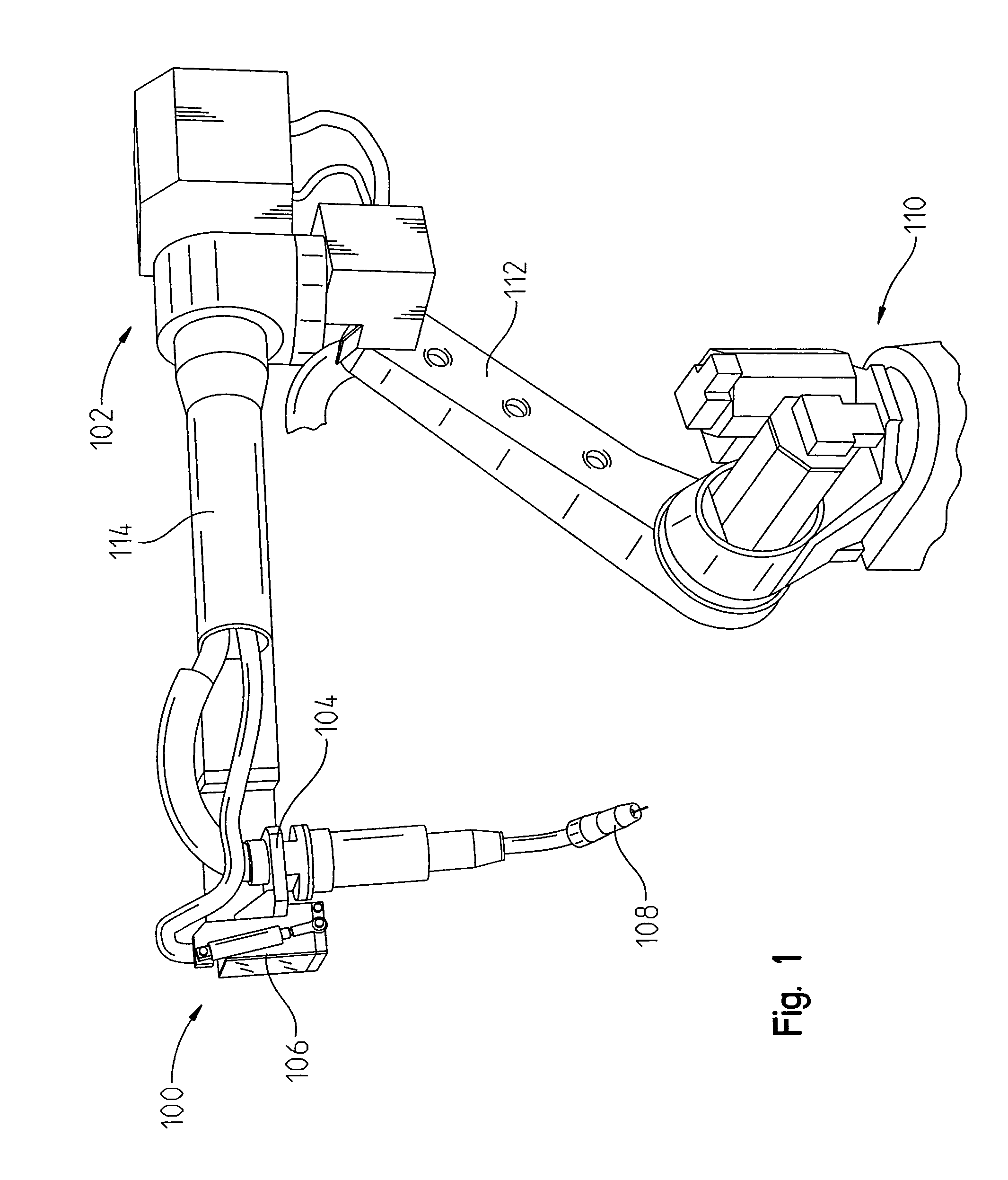
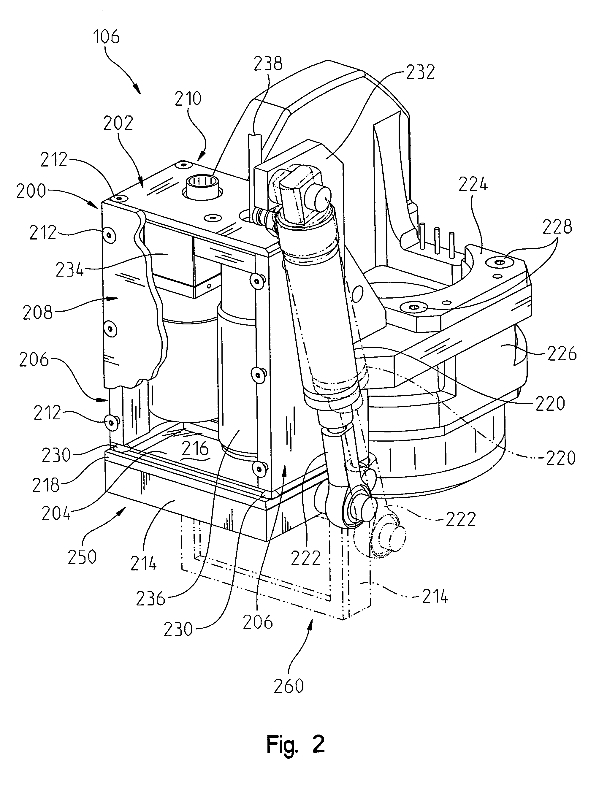
[0015]In the present disclosure, the vision enclosure assembly provides an enclosure for protecting an image-recording device (e.g., camera) and a light source from smoke, dust, fumes, spatter, and temperature variation during a welding operation. As a result, the enclosure assembly can be disposed near the welding tool and video or pictures can be taken of a welded product with better images.
[0016]The enclosure assembly can be conveniently mounted to a robotic arm and thus positioned in an industrial setting for recording or producing images of the welding operation. A light source can advantageously emit light to allow for enhanced quality video or images to be recorded by the image-recording device. Further, the size of the enclosure panel is small enough so that the robotic arm does not have reduced mobility.
[0017]In addition, since the enclosure assembly can be mounted to a robotic arm in close proximity to the materials being welded, a robot can perform the welding without subjecting a human being to the hazards and risks associated with a normal welding process.

Problems solved by technology

The welding process can be hazardous and care is taken to avoid burns, electric shock, vision damage, inhalation of poisonous gases and fumes, and exposure to intense ultraviolet radiation.
Second, the robot can often work autonomously for many hours, days, or weeks without stopping.
Since the robot continuously moves during the welding process, it often difficult to monitor or visualize the welding process.
Further, smoke, dust, fumes, and spatter can often be emitted during the welding process which further blurs or blocks one from observing the process.
Video equipment can be used to record the process, but the emissions from the process itself often makes it difficult to clearly see the welding or the finished product.
In addition, industrial settings can often be dark and the lack of a light source directed onto the welded materials further inhibits an observer from visualizing the welding process or the finished product.

Method used


Image

  • Protective enclosure
  • Protective enclosure
  • Protective enclosure

Examples


Embodiment Construction

[0025]The embodiments of the present invention described below are not intended to be exhaustive or to limit the invention to the precise forms disclosed in the following detailed description. Rather, the embodiments are chosen and described so that others skilled in the art may appreciate and understand the principles and practices of the present invention.

[0026]In the present disclosure, an enclosure assembly is provided for use in any industrial or hazardous working environment. The enclosure assembly can be used especially in welding environments and be removably coupled to a robot that performs the welding. However, the enclosure assembly is not limited to welding environments and may also be useful for industrial painting environments, test cells, etc. The enclosure assembly is further suitable for housing equipment such as video recording devices, cameras, light sources, computers, audio recording devices, monitors, sensors and the like. The enclosure assembly may also be sui...


PUM

PropertyMeasurementUnit
Lengthaaaaaaaaaa
Transparencyaaaaaaaaaa
Lightaaaaaaaaaa

Abstract

The present disclosure provides a system for carrying out a welding process. The system includes a controllable robot having a robotic arm and a welding device coupled to the robotic arm. The welding device is configured to perform the welding process. The system also includes a housing coupled to the robotic arm adjacent the welding device and a closure member pivotably coupled to one end of the housing. The closure member is adapted to pivot between an open position and a closed position. A camera is disposed in the housing and removably coupled thereto. The camera has a lens oriented towards the closure member. The system further includes a light source disposed in the housing and removably coupled thereto such that the light source is disposed adjacent to the camera. During the welding process, the camera and light source are enclosed by the housing and closure member.

Description

FIELD OF THE INVENTION[0001]The present invention relates to a protective enclosure, and in particular to a protective enclosure for protecting electronic devices in an extreme welding environment.BACKGROUND OF THE INVENTION[0002]Welding is a well-known fabrication process for joining two or more materials, e.g., metals or thermoplastics. Welding often takes place in an industrial setting and uses a gas flame, an electric arc, a laser, an electron beam, friction or ultrasound as an energy source. The welding process can be hazardous and care is taken to avoid burns, electric shock, vision damage, inhalation of poisonous gases and fumes, and exposure to intense ultraviolet radiation.[0003]In industrial settings, many functions can be performed by a robot or the like. This is advantageous for several reasons. First, it is safer having a robot carry out dangerous functions rather than a human being. Second, the robot can often work autonomously for many hours, days, or weeks without st...

Claims


Application Information

Patent Timeline
IPC IPC(8): B23K11/00B65D71/00
CPCB23K37/00B25J19/023B23K26/427B23K37/006B23K9/321B23K26/706
Inventor GNEITING, RYAN M.KENNICKER, ALLEN M.
Owner DEERE & CO
Learn More