Mass spectrometer and mass analyzing method

Active Publication Date: 2012-12-27
HITACHI HIGH-TECH CORP
View PDF17 Cites 38 Cited by
  • Summary
  • Abstract
  • Description
  • Claims
  • Application Information

AI Technical Summary

Benefits of technology

[0013]According to the present invention, ionization with inconsiderable fr

Problems solved by technology

According to a configuration described in US 2010/0243884 A1, a preparatory exhaust chamber is needed between the sample vaporizing chamber and the atmosphere for introducing the probe from a side of the atmosphere to the sample vaporizing chamber, a structure thereof becomes complicated, and therefore, the configuration is disadvantageous for downsizing.
Moreover, an ion loss in a transfer line is brought about when the sample gas moves from the sample vaporizing chamber the ionization source, which gives rise to a deterioration in a sensitivity.
The fragme

Method used


Image

  • Mass spectrometer and mass analyzing method
  • Mass spectrometer and mass analyzing method
  • Mass spectrometer and mass analyzing method

Examples


first embodiment

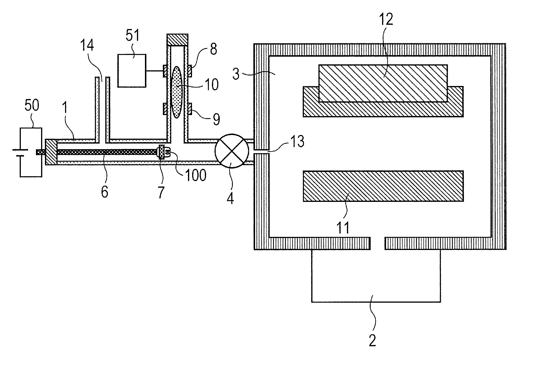
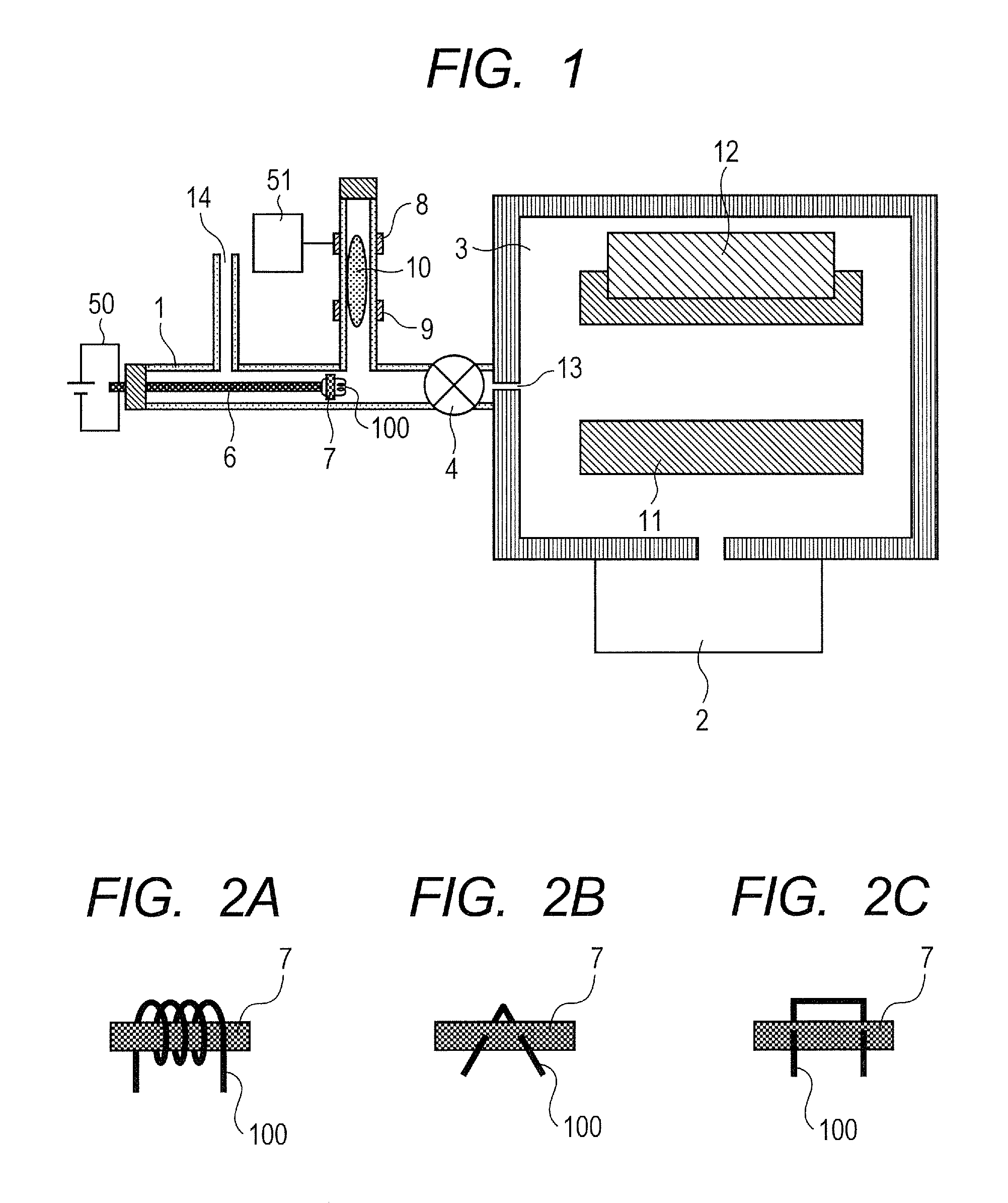
[0030]FIG. 1 is a configuration view showing an embodiment of a mass spectrometer according to the present invention. The mass spectrometer is mainly configured by an ionization source 1 made of a dielectric substance of glass, plastic, ceramic, resin etc. and a vacuum chamber 3 a pressure of which is maintained to be equal to or lower than 10−1 Pa by a vacuum pump 2. The ionization source 1 and the vacuumed chamber 3 are partitioned by a valve 4. The ionization source 1 is typically a pipe having an outer diameter of about 4 mm and an inner diameter of about 1 through 4 mm.

[0031]A sample introduction probe 6, having a resistance heating filament 100 at a tip end thereof, and to which the current can be made to flow from outside, is inserted into the ionization source 1. Here is exemplified a mode of inserting the sample introduction probe 6 having a handle to the cylindrical ionization source 1. The tip end of the sample introduction probe 6 is attached with the resistance heating ...

second embodiment

[0046]FIG. 8 is a configuration view showing an embodiment of the mass spectrometer according to the present invention. The vacuumed chamber 3 is similar to that of the first embodiment and an illustration thereof will be omitted. The pressure condition of the discharge produced plasma 10 and the output voltage of the power source 51 are also similar to those of the first embodiment. Different from the first embodiment, according to the second embodiment, the sample 7 adhered to the tip end of the sample introduction probe 6 is vaporized by introducing a gas from a high temperature gas generating source 16 to the ionization source 1 through the gas introducing slender pipe 14. Therefore, the resistance heating filament 100 is not needed at the tip end of the sample introduction probe 6, and it is not necessary to connect a power source to the sample introduction probe 6. It is necessary to directly coat the sample 7 at the tip end of the sample introduction probe 6, or fix an adsorb...

third embodiment

[0047]FIG. 9 is a configuration view showing an embodiment of the mass spectrometer according to the present invention. The vacuumed chamber 3 is similar to that of the first embodiment and the illustration will be omitted. The pressure condition of the plasma 10 and the outputted voltage of the power source 51 are also similar to those of the first embodiment. Different from the first and the second embodiments, a portion in the ionization source 1 for generating the discharge produced plasma 10 is arranged coaxially with the sample introduction probe 6. So far as the portion is coaxial with the sample introduction probe 6, the discharge produced plasma 10 may be generated between the sample 7 and the valve 4 or on a side of the gas introducing slender pipe 14 relative to the sample 7. The sample 7 may be exposed directly to the discharge produced plasma 10. Or, as shown in FIG. 10, the sample introduction probe 6 is made to be one of the discharge electrodes, and the discharge pro...


PUM


Abstract

A mass spectrometer including a sample attaching member of attaching a sample, an ionizing chamber including an introductory port of the sample attaching member and an ionization source of generating a sample ion, a vacuumed chamber having a mass analyzer of analyzing the sample ion, and an opening/closing mechanism provided between the ionizing chamber and the vacuumed chamber, in which the opening/closing mechanism is controlled from a closed state to an open state after introducing the sample attaching member into the ionizing chamber to thereby enable to perform ionization with inconsiderable fragmentation at a high sensitivity with a high throughput

Description

CLAIM OF PRIORITY[0001]The present application claims priority from Japanese patent application JP 2011-141388 filed on Jun. 27, 2011, the content of which is hereby incorporated by reference into this application.FIELD OF THE INVENTION[0002]The present invention relates to a mass spectrometer and a method of operating the same.BACKGROUND OF THE INVENTION[0003]In a mass spectrometer, there are a number of methods of transporting liquid and solid samples to an ionization source. Above all, an explanation will be given as follows of sample introduction using a probe of introducing a sample directly to an ionization source or a vicinity thereof.[0004]US 2010 / 0243884 A1 describes a method of introducing a probe holding a sample to a sample vaporizing chamber at a vicinity of an ionization source under a reduced pressure. According to the method, a sample is vaporized by heating the probe, and a sample gas is introduced to the ionization source by making a gas flow from the sample vapori...

Claims


Application Information

Patent Timeline
IPC IPC(8): H01J49/04
CPCH01J49/0495H01J49/0409
Inventor KUMANO, SHUNSUGIYAMA, MASUYUKIHASHIMOTO, YUICHIROHASEGAWA, HIDEKIYAMADA, MASUYOSHIMOROKUMA, HIDETOSHIHASHIBA, SHUHEI
Owner HITACHI HIGH-TECH CORP
Why Eureka
Try Eureka