Image display apparatus

a technology of image display and heat releasing member, which is applied in the direction of color television details, instruments, projectors, etc., can solve the problems of high manufacturing cost, detected by the temperature sensor, etc., and achieve the effect of improving the heat releasing ability of the laser light source apparatus, easy compactness, and easy assembly

Inactive Publication Date: 2012-12-27
PANASONIC CORP
View PDF0 Cites 20 Cited by
  • Summary
  • Abstract
  • Description
  • Claims
  • Application Information

AI Technical Summary

Benefits of technology

[0014]An advantage of the present invention is to provide an image display apparatus which increases the heat releasing ability of a laser light source apparatus and which is capable of being miniaturized.
[0015]In order to achieve this, the image display apparatus of the present invention includes a first laser light source apparatus which emits laser light of one of a red color, a green color, and a blue color; a second laser light source apparatus which emits one of another of the colors of laser light; a third laser light source apparatus which emits the remaining color of laser light; and a cooling fan which distributes cooling air which cools each of the laser light source apparatuses. The first laser light source apparatus includes a heat releasing member. The heat releasing member has a configuration integrally including a tubular portion and a wall portion. The wall portion extends from the tubular portion to catch the cooling air distributed from the cooling fan to guide the cooling air to the tubular portion, through which the cooling air passes. Accordingly, the heat releasing member distributes cooling air from the cooling fan to cool the laser light source apparatuses and the cooling ability of the heat releasing member is improved because the tubular portion through which the cooling air passes and the wall portion guiding the cooling air to the tubular portion are integrally provided on the heat releasing member. The heat releasing member may be provided, for example, on the laser light source apparatus among each of a red color, green color, and blue color that produces the greatest amount of heat. A configuration in which cooling air is distributed to the other laser light source apparatuses is possible and, in addition, due to the tubular portion having a shape through which the cooling air passes, there are no projecting portions as in a heat releasing member provided with fins. The heat releasing member may thus be easily made compact, as well.
[0016]It is desirable that the cooling air distributed from the cooling fan be configured to flow across the back in the optical axis direction of the first laser light source apparatus to reach the wall portion, then that the wall portion alter the flow toward the tubular portion positioned on a side in the optical axis direction of the first laser light source apparatus. Moreover, it is desirable that the tubular portion have an axial direction length of a roughly equal length to the first laser light source apparatus. It is further desirable that the wall portion be formed with a length projecting out from the first laser light source apparatus. Accordingly, in a case where the heat releasing member has been mounted on the first laser light source apparatus, it is possible to catch the cooling air with the wall portion projecting from the first laser light source apparatus. It is further possible to favorably guide the cooling air along the wall portion to the tubular portion.
[0017]Yet further, it is preferable that one of the second and third laser light source apparatuses be disposed on a downstream side of the cooling air with respect to the heat releasing member. Thereby, due to the configuration of the heat releasing member in which cooling air passes through the tubular portion, a flow of cooling air develops downstream from the tubular portion. Moreover, the directionality of the flow of cooling air may be stabilized by passing through the tubular portion, and thus the distribution of cooling air to the laser light source apparatuses provided downstream may also be stabilized, and cooling ability may be improved.
[0018]In order to provide an image display apparatus which increases the heat releasing ability of a laser light source apparatus and which is also able to be miniaturized, the image display apparatus of the present invention includes a first laser light source apparatus emitting one of a red color, a green color, and a blue color laser light; a second laser light source apparatus emitting one of the other colors of laser light; and a third laser light source apparatus emitting the remaining color of laser light. The image display apparatus further includes a cooling fan delivering cooling air to cool each laser light source apparatus; a temperature sensor detecting the temperature of the second laser light source apparatus; and an air flow blocker preventing the distribution of cooling air to the temperature sensor.
[0019]With this configuration, when a red color semiconductor laser is employed in the second laser light source apparatus, there is a tendency for light emission of the red color semiconductor laser to drop increasingly as temperature rises. Therefore, a greater amount of cooling air is delivered to the red color laser light source apparatus in order to inhibit a rise in temperature. A temperature sensor is mounted to the second laser light source apparatus in order to reliably control the temperature of the red color laser light source apparatus. In addition, an air flow blocker is provided protecting the temperature sensor from the cooling air such that the temperature sensor is not affected by the cooling air. Accordingly, the temperature of the second laser light source apparatus may be accurately detected. In addition, the temperature of the first and third laser light source apparatuses may be accurately estimated without mounting individual temperature sensors thereon.

Problems solved by technology

However, due to the difficulty of mass producing a semiconductor laser emitting a pure green color laser light, a green color laser light source apparatus may employ, for example, a solid-state laser element and a wavelength conversion element to emit green color laser light, the solid-state laser element emitting infrared laser light and the wavelength conversion element converting the wavelength of the infrared laser light and emitting half-wavelength laser light, which constitutes green color laser light.
Furthermore, because laser light causes damage upon entering the eye, standards have been established regarding the safety of laser products (IEC 60825-1).
However, the relationship between the drive electric current value of a semiconductor laser and the energy concentration of the light radiated to the exterior from the semiconductor laser is not constant, and fluctuates according to the temperature of the semiconductor laser itself This means that the fluctuation is dependent on the ambient temperature of the surroundings, of course, but also dependent on the amount of radiation time.
In such a case, mounting a temperature sensor on each of the red, green, and blue laser light source apparatuses is not only difficult because the mounting locations and wiring space are highly restricted, but manufacturing costs also rise sharply.
However, depending on the relationship between the placement of the temperature sensor and the flow path of cooling air, the temperature detected by the temperature sensor may not be the actual temperature of the laser light source apparatus.

Method used


Image

  • Image display apparatus
  • Image display apparatus
  • Image display apparatus

Examples


Embodiment Construction

[0046]The particulars shown herein are by way of example and for purposes of illustrative discussion of the embodiments of the present invention only and are presented in the cause of providing what is believed to be the most useful and readily understood description of the principles and conceptual aspects of the present invention. In this regard, no attempt is made to show structural details of the present invention in more detail than is necessary for the fundamental understanding of the present invention, the description is taken with the drawings making apparent to those skilled in the art how the forms of the present invention may be embodied in practice.

[0047]Hereinafter, an embodiment of the present invention is described with reference to the drawings.

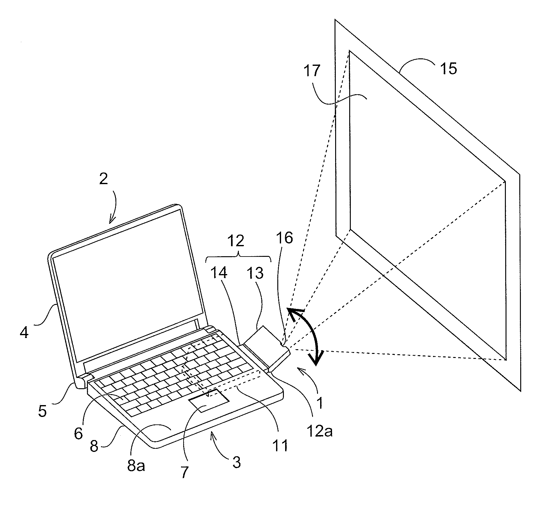
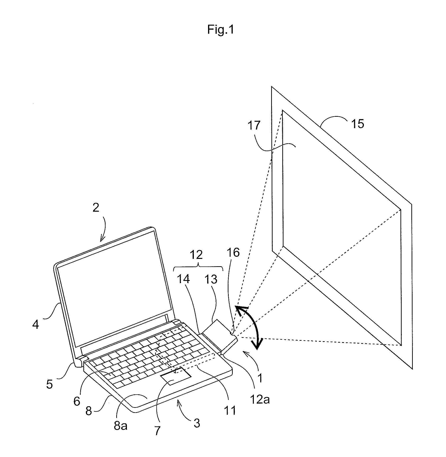
[0048]FIG. 1 is a perspective view illustrating an example of an image display apparatus 1 according to the present invention installed in a portable information processing apparatus 2. The portable information processing appa...


PUM


Abstract

An image display apparatus including a laser light source apparatus with a semiconductor laser as a light source increases the heat releasing ability of the laser light source apparatus in the image display apparatus. In order to accomplish this, a heat sink is provided to a green color laser light source apparatus, which generates green color light by wavelength conversion from infrared light and, therefore, produces a greater amount of heat than the other laser light source apparatuses. In addition, an air flow blocking cover is mounted on the surface of the holder, covering the temperature sensor, to prevent distribution to the temperature sensor of cooling air from the cooling fan disposed adjacent to the red color laser light source apparatus. It is thus possible to comply with laser safety standards.

Description

CROSS-REFERENCE TO RELATED APPLICATIONS[0001]The present application claims priority under 35 U.S.C. §119 of Japanese Application No. 2011-142107, filed on Jun. 27, 2011, and of Japanese Application No. 2011-142080, filed on Jun. 27, 2011, the disclosures of which are expressly incorporated by reference herein in their entirety.BACKGROUND OF THE INVENTION[0002]1. Field of the Invention[0003]In order to control temperature changes in a laser light source apparatus, the present invention relates to an image display apparatus in which a temperature sensor is mounted to the laser light source apparatus employing a semiconductor laser, and further relates to an image display apparatus which includes a heat releasing member.[0004]2. Description of Related Art[0005]In recent years, focus has been on technology employing a semiconductor laser as a light source for a projection-type image display apparatus which projects an image onto a screen. A semiconductor laser has various advantages as...

Claims


Application Information

Patent Timeline
Patent Type & Authority Applications(United States)
IPC IPC(8): G03B21/16
CPCG03B21/16G03B21/145G03B21/2033H04N9/3173G03B33/06H04N9/3144H04N9/3161G03B21/2086
Inventor ENOMOTO, HIROFUMITESHIMA, YOSHIHIROMUTOH, JUNICHI
Owner PANASONIC CORP
Why Eureka
Try Eureka