
Immersion type sensor for measuring temperature

a technology of immersion-type sensors and temperature, which is applied in the direction of thermometers, radiation pyrometry, instruments, etc., can solve the problems of difficult quantification and elimination, inability to meet the requirements of several applications, so as to improve emissivity and prolong the residence time in molten metal

Inactive Publication Date: 2012-12-27
GODA JYOTI
View PDF10 Cites 11 Cited by
  • Summary
  • Abstract
  • Description
  • Claims
  • Application Information

AI Technical Summary

Benefits of technology

[0014]A further object of the invention is to provide for advancement in immersion-type temperature measurement devices which would minimize the effects of variations in object emissivity, external radiation sources and changes in emissivity of external radiation sources on the measured temperature.
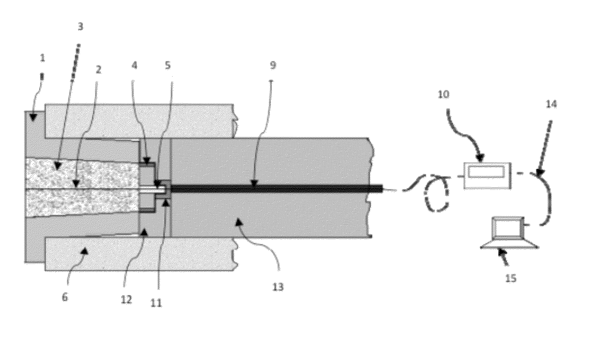
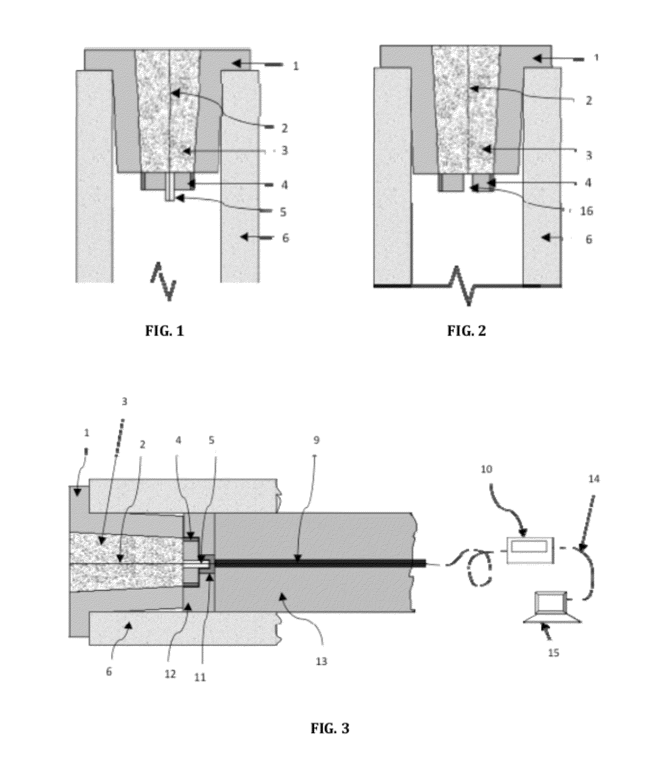
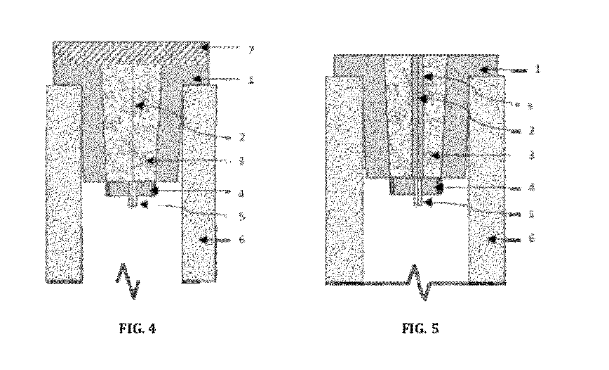
[0057]This sensor is immersed into the molten metal by means of a lance that is made of metal or ceramic or other materials capable of withstanding temperatures in the range of 1500°-1700° C. Within the lance is contained an armored optical fiber which is connected to the optical fiber in the probe via a contact block. The lance is protected from the liquid metal by a protective coating that is composed of paperboard or other suitable insulating materials depending on the duration of the immersion of the sensor in the molten metal, and is firmly attached to the probe via an adhesive. The paper board is wound tightly into a paper tube and with a suitable adhesive so that it does not burn in contact with the molten meal but burns layer by layer and gives adequate time for the immersion and withdrawal of the sensor from the molten metal.

Problems solved by technology

Traditionally, the immersion type thermoelectric temperature sensors are based on thermocouples but these are not viable in several applications.
The major drawback of non-contact pyrometry is that the incident radiation is received not only from the hot body to be measured but other hot bodies that are invariably present in the vicinity.
These bodies have different emissivities and introduce complex errors that are difficult to quantify and eliminate.
In general, non-contact pyrometry techniques have high errors and some might be outside the tolerance of those acceptable to the industry.
However, as a consequence of using the optical fiber in a reel form a length of fiber equal to the thickness of the slag is always wasted on each immersion.
This causes losses of the expensive optical fiber during each measurement.
A second problem associated with the presently available contact / immersion type measurements is that when the tip of the optical fiber which is metal-covered is kept immersed into the molten steel for a long time after detecting the temperature of the molten steel, the metallic coating layer of the optical fiber becomes gaseous in the high temperature environment.
The third drawback is that the signal from the hot body is significantly attenuated along the length of the fiber.
Thus, the signal received by the radiation thermometer is weak and the signal to noise ratio is low.
This introduces errors into the measurement.
The fourth limitation is that the above discussed techniques are designed to be continuous measurement techniques and are not suitable in areas where only instantaneous temperature at critical instances of time is required.
This leads to economic inefficiency
Apart from the above constructional limitations of the present available measuring systems, it is also experienced that such systems also have some limitations in achieving accurate and faster measurement of temperature.
However, on account of the quantity of data to be handled to accurately predict the temperature, multi-wavelength pyrometry tends to involve intense, time-consuming processing steps.
Thus all such known techniques especially contact type temperature sensor for the measurement of molten metal temperature are either devices which are complex and / or cost extensive to use and hence not convenient for wide scale repetitive use for measurement of temperature of the molten metal and / or have limitations in reaching to the desired accurate and faster determination of temperature of molten metal / steel.

Method used


Image

  • Immersion type sensor for measuring temperature
  • Immersion type sensor for measuring temperature
  • Immersion type sensor for measuring temperature

Examples


example

Measurement of Molten Temperature Involving the System of the Present Invention

[0078]For the purposes of measurement of the molten metal temperature the immersion type sensor for measurement of temperatures of molten metal in accordance with the present invention was used.

[0079]For the purposes of measurement the following steps were followed:

[0080]immersing the probe receptacle having an optical fiber into the molten metal;[0081]a. b. collecting the optical signals including emitted radiations from the molten metal via the optical fiber housed in the probe receptacle;[0082]b. directing the optical signal towards the detector module and carrying out processing of the optical signal in said detector module to measure the temperature of molten metal involving the combination of two color pyrometry and multi-color pyrometry.

[0083]A comparative molten metal temperature measurement was studied following the method involving the system of the invention as above with respect to related dat...


PUM


Abstract

A device for measuring the temperature of molten metal irrespective of the nature of the metal, particularly, an immersion / contact type temperature sensing device involving optical fiber which can be universally used for different materials and would be adapted for safe and repetitive immersion in molten metal for measurement of molten metal temperatures and the like. The proposed immersion / contact type temperature sensing device involves combination two-color and multi-color pyrometric detection technique is capable of cost effective and discrete-time temperature measurement of molten metal. The advancement is thus directed to serve as a ready and fast accurate measurement of molten metal temperature and the like.

Description

CROSS-REFERENCE TO RELATED APPLICATION AND CLAIM OF PRIORITY[0001]This application claims priority to Indian Patent Application No. 839 / KOL / 2011, filed on Jun. 24, 2011, which is incorporated herein by reference in its entirety.BACKGROUND[0002]1. Field of the Invention[0003]The present invention relates to advancements in measurement of temperature of molten metal and the like and, in particular, to advancements in immersion-type sensor for measurement of temperature of molten metals and more particularly to an optical fiber based temperature sensor. Importantly, the sensor of the invention is directed to a user friendly and cost effective discrete-time temperature measurement of molten metal. Advantageously the invention directed towards the development of a temperature sensor device, which is invulnerable to external electromagnetic radiation, is cost effective and not prone to changes in material emmissivities and can be used to measure the temperature of the molten metal irrespe...

Claims


Application Information

Patent Timeline
IPC IPC(8): G01K13/00G01K1/12
CPCG01J5/004G01J5/0821G01J5/048
Inventor GODA, JYOTI
Owner GODA JYOTI
Learn More