Systems and devices for intralumenal implantation

a technology of system and device, applied in the field of intralumenal implantation, can solve the problems of long-term recanalization of aneurysms, hemorrhagic stroke, symptomatic neurological deficits, etc., and achieve the effect of reducing the volume of fluid available and more control over the deployment of medical devices

Inactive Publication Date: 2012-12-27
JONES DONALD K +1
View PDF30 Cites 26 Cited by
  • Summary
  • Abstract
  • Description
  • Claims
  • Application Information

AI Technical Summary

Benefits of technology

[0014]In accordance with another aspect of the present invention there is provided a medical device deployment system. The medical device deployment system includes a medical device, a delivery catheter and an inflation source member. The delivery catheter includes a longitudinally extending balloon member coupled to its distal end which is everted and positioned within the catheter lumen. The medical device is positioned at the distal end of the delivery catheter and disposed within the lumen of the catheter within the everted balloon member. The delivery catheter further includes a flow restriction member positioned within the catheter lumen proximal to the everted balloon and medical device. The flow restriction member is preferably formed as tubular member having lumen substantially smaller than the lumen of the catheter. The flow restriction member may be formed of a metal, ceramic, polymer or any mixture thereof and have dimensional characteristics that do not significantly impact the ability of t

Problems solved by technology

Under cerebral flow conditions the weakened vessel wall forms a bulge or aneurysm which can lead to symptomatic neurological deficits or ultimately a hemorrhagic stroke when ruptured.
One drawback associated with the use of bare embolization coils relates to the inability to adequately pack or fill the aneurysm due to the geometry of the coils which can lead to long term recanalization of the aneurysm with increased risk of rupture.
For instance, in the case of bioactive coils, the materials eliciting the biological healing response are somewhat difficult to integrate with the coil structure or have mechanical properties incompatible with those of the coil making the devices difficult to accurately position within the aneurysm.
This expansion may be immediate or time delayed but is generally, at some point, out of the control of the physician.
With a time delayed response the physician may find that coils which were initially placed accurately and detached become dislodged during the expansion process leadin

Method used


Image

  • Systems and devices for intralumenal implantation
  • Systems and devices for intralumenal implantation
  • Systems and devices for intralumenal implantation

Examples


Embodiment Construction

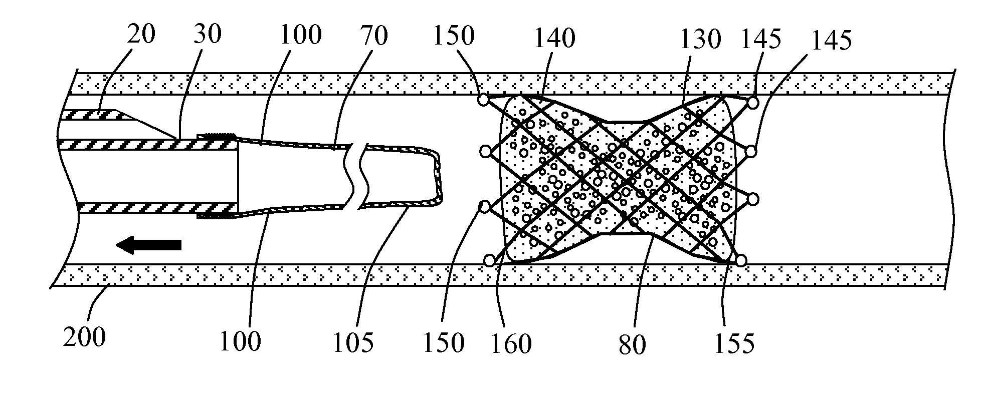
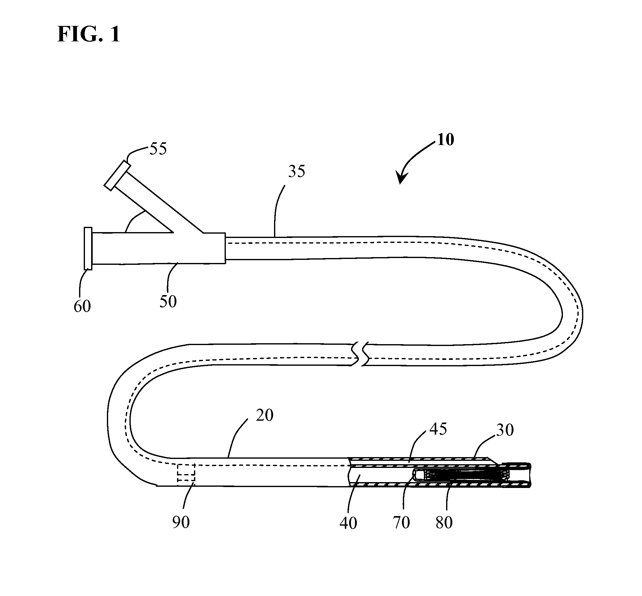
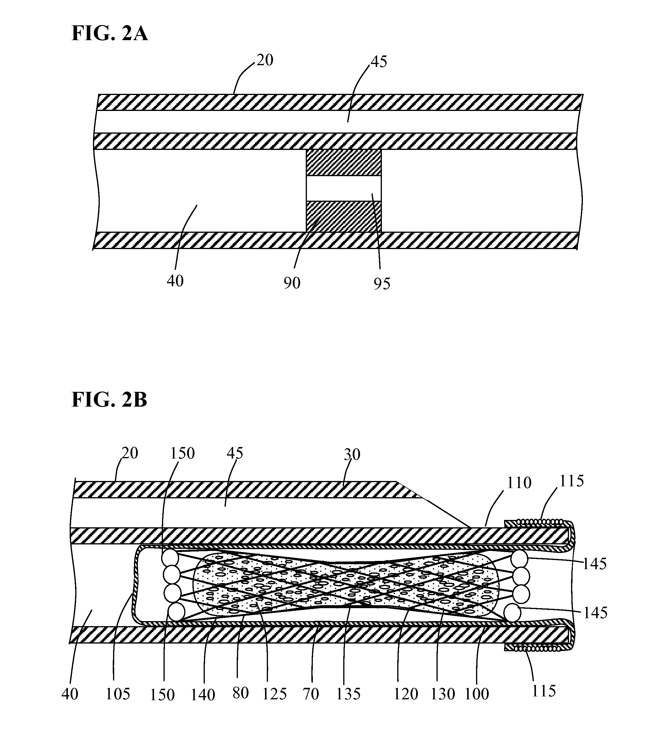
[0025]Methods and systems for implanting a medical device in a desired area of the body are herein described. FIG. 1 illustrates a medical device deployment system 10 suitable for use with embodiments of the present invention. Deployment system 10 includes an elongate tubular catheter 20 having distal and proximal ends 30 and 35 respectively, a deployment lumen 40 and a guidewire lumen 45 extending from proximal end 35 to distal end 30. A catheter hub 50 is coupled to the proximal end 35 of catheter 20. Catheter hub 50 includes a guidewire port 55 in fluid communication with guidewire lumen 45 and a deployment port 60 in fluid communication with deployment lumen 40. An elongate balloon member 70 is coupled to and positioned within deployment lumen 40 at catheter distal end 30. Occlusion device 80 is positioned within deployment lumen 40 inside of everted balloon member 70. Positioned within deployment lumen 40 of catheter 20, proximal to balloon member 70 is flow restriction member ...


PUM


Abstract

Devices, systems and methods are provided for performing intra-lumenal medical procedures in a desired area of the body. Medical devices including filter devices, embolization devices, stents, delivery systems and methods of performing medical procedures to occlude, filter, redirect and or re-establish the intravascular flow of blood are provided for the treatment of hemorrhagic and ischemic disease states.

Description

CROSS-REFERENCE TO RELATED APPLICATIONS[0001]This application claims the benefit of U.S. Provisional Application No. 61 / 501,742 filed Jun. 27, 2011, U.S. Provisional Application No. 61 / 501,745 filed Jun. 27, 2011 U.S. Provisional Application No. 61 / 501,746 filed Jun. 27, 2011 and U.S. Provisional Application No. 61 / 501,747 filed Jun. 27, 2011 all of which are hereby incorporated by reference herein in their entireties.BACKGROUND OF THE INVENTION[0002]The field of intralumenal therapy for the treatment of vascular disease states has for many years focused on the use of many different types of therapeutic devices. While it is currently unforeseeable that one particular device will be suitable to treat all types of vascular disease states it may however be possible to reduce the number of devices used for some disease states while at the same time improve patient outcomes at a reduced cost. To identify potential opportunities to improve the efficiency and efficacy of the devices and pr...

Claims


Application Information

Patent Timeline
IPC IPC(8): A61M29/02
CPCA61F2/01A61F2/958A61F2/962A61F2002/011A61B2017/12081A61B17/12109A61B17/12172A61B17/12177A61B17/1219A61F2/95A61F2/0105A61F2/011
Inventor JONES, DONALD K.MITELBERG, VLADIMIR
Owner JONES DONALD K
Why Eureka
Try Eureka