Recycling co2 in heavy oil or bitumen production

a technology of heavy oil or bitumen and co2 is applied in the field of thermoplastic production methods, which can solve the problems of large amount of water and energy required to inject steam, high cost of process, and relatively insensitive process, and achieve the effect of maximizing efficiency and minimizing costs

Active Publication Date: 2013-01-03
CONOCOPHILLIPS CO
View PDF11 Cites 7 Cited by
  • Summary
  • Abstract
  • Description
  • Claims
  • Application Information

AI Technical Summary

Benefits of technology

[0025]“Recycled CO2” refers to CO2 that is not generated for the sole purpose of being injected to the formation, and may include CO2 generated as a byproduct of generating the steam to be used in a steam-assisted production process. The CO2 need not be pure, but can have other gases admixed therewith. However, greatly enriched CO2 is preferred as this provides the most CO2 sequestration. Preferably, the CO2 is produced at or near the reservoir, as this minimizes costs and maximizes efficiency, e.g., as a byproduct of steam production (e.g., onsite burning of fuel to make steam). However, this is not an essential feature, and the CO2 can also be transported to the site for injection.

Problems solved by technology

Such processes can use more water and require larger amounts of energy than conventional oil extraction, although many conventional oil fields also require large amounts of water and energy to achieve good rates of production.
The CSS method has the advantage that recovery factors are around 20 to 25% and the disadvantage that the cost to inject steam is high.
The process is relatively insensitive to shale streaks and other vertical barriers to steam and fluid flow because, as the rock is heated, differential thermal expansion causes fractures in it, allowing steam and fluids to flow through.
Additionally, heat losses to over and under burdens have negative impact on economics or may even limit the applicability of thermal recovery processes.
The heat loss problem is seldom directly dealt with and often shunned by resorting to a less effective and more time-consuming non-thermal recovery process.
However, existing methodologies use CO2 at or near the production well, which has disadvantages.
First, CO2 partial pressure will detrimentally affect the saturation temperature of the injected stream.
However, when co-injected with steam, it tends to stay ahead of the steam chamber and hence limits the development of steam chamber.

Method used


Image

  • Recycling co2 in heavy oil or bitumen production
  • Recycling co2 in heavy oil or bitumen production
  • Recycling co2 in heavy oil or bitumen production

Examples


example 1

Simulation of CO2 Injection

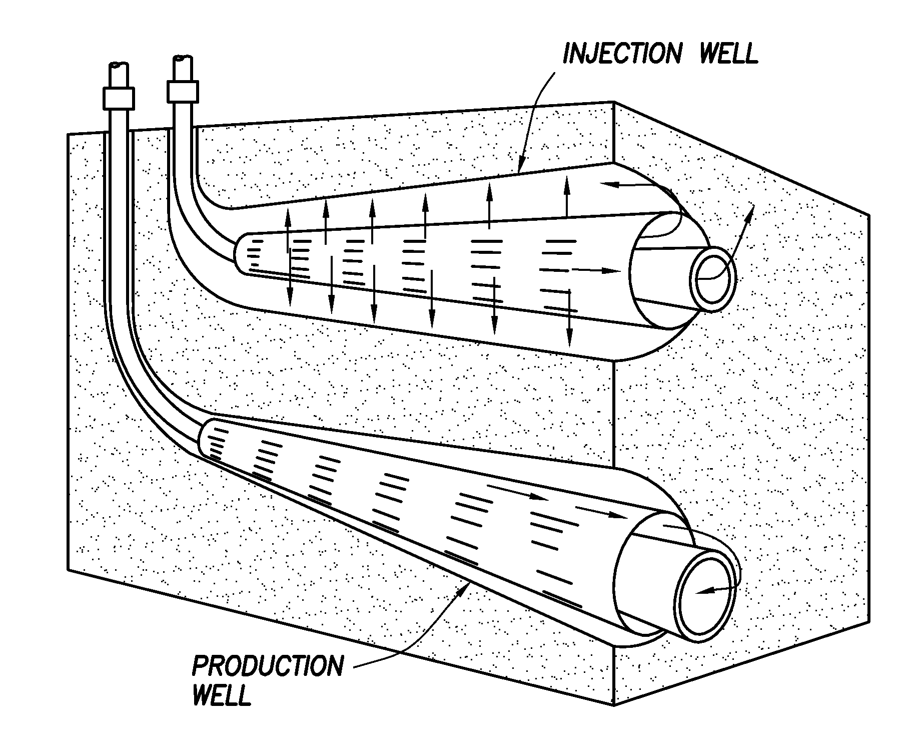
[0040]The modeling work with CMG STARS, a commercial modeling software well accepted by the industry for thermal simulation, is shown in FIGS. 1, 2 and 3. The modeling assumes a horizontal target well that is 50 meters away from horizontal producer and steam injection well pair and at or near the top of the pay zone.

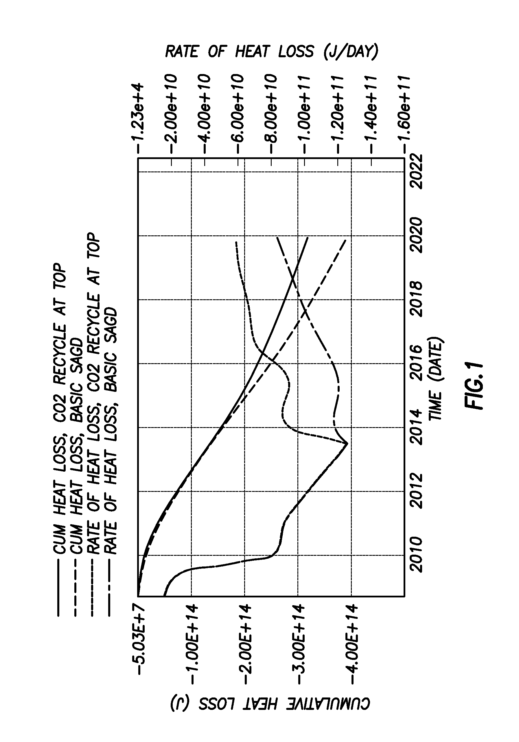
[0041]FIG. 1 is the simulated results using CMG STARS to predict the cumulative and rate of heat loss with or without using the method of the present embodiment.

[0042]As can be seen in FIG. 1, the rate of heat loss to over and under burdens in the case using the method of the present embodiment are reduced by about 20% as compared to conventional method. Additional efficiencies might be realized by sandwiching the steam injection well between a pair of target CO2 injection wells, thus ensuring good insulating and solvating coverage of the pay zone by the injected CO2.

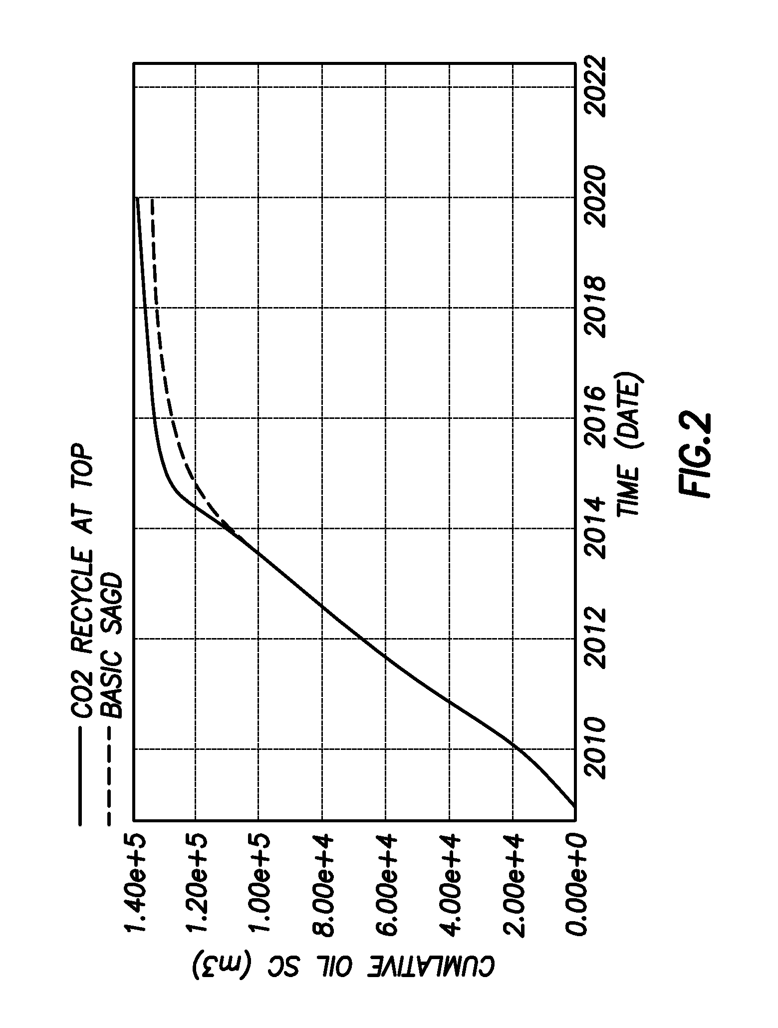
[0043]Additionally, FIG. 2 shows the simulated results of oil recovery by usin...


PUM


Abstract

A method relates to improving production rate and recovery of heavy oil or bitumen and reducing heat loss to over and under burden in a steam-assisted production process. The method includes strategically injecting recycled carbon dioxide into the reservoir between production wells. The heat insulation and solvent effects provided by carbon dioxide dissolved in the oil phase facilitate the desired improvement on oil recovery, and simultaneously sequester the CO2 back into the reservoir.

Description

CROSS-REFERENCE TO RELATED APPLICATIONS[0001]This application is a non-provisional application which claims benefit under 35 USC §119(e) to U.S. Provisional Application Ser. No. 61 / 502,165 filed Jun. 28, 2011, entitled “Recycling CO2 in Heavy Oil or Bitumen Production,” which is incorporated herein in its entirety.STATEMENT REGARDING FEDERALLY SPONSORED RESEARCH OR DEVELOPMENT[0002]None.FIELD OF THE INVENTION[0003]A method relating to thermal production methods, such as steam-assisted gravity drainage (SAGD) and cyclic steam stimulation (CSS) production methods, which are improved by the injection of CO2 at some distance from the production well(s). The advantage of this embodiment is demonstrated in a SAGD process, but is applicable to any thermal or steam assisted production process.BACKGROUND OF THE INVENTION[0004]Bitumen (colloquially known as “tar” due to its similar appearance, odor, and color) is a thick, sticky form of crude oil, so heavy and viscous (thick) that it will not...

Claims


Application Information

Patent Timeline
Patent Type & Authority Applications(United States)
IPC IPC(8): E21B43/24
CPCE21B43/164E21B43/305E21B43/2408Y02P90/70
Inventor FANG, WINDSONGWHEELER, THOMAS J.
Owner CONOCOPHILLIPS CO
Why Eureka
Try Eureka