
System level power delivery to a plasma processing load

Inactive Publication Date: 2013-01-03
AES GLOBAL HLDG PTE LTD
View PDF4 Cites 32 Cited by
  • Summary
  • Abstract
  • Description
  • Claims
  • Application Information

AI Technical Summary

Benefits of technology

This patent discusses a system and methods for controlling power delivery to a plasma load. The system includes a generator, match network, and plasma load, which are monitored and controlled by a local controller. The monitored characteristics include the generator's power output, which is analyzed and relayed to the controller. The resulting information is used to adjust the generator and match network simultaneously, improving power delivery accuracy and consistency to the plasma load. The technical effects are improved power delivery accuracy and consistency to the plasma load.

Problems solved by technology

The continued drive for ever shrinking features in semiconductor manufacturing poses significant challenges for tool manufacturers and process developers alike.
A human operator typically monitors multiple sensor outputs from a generator and a match network and adjusts numerous parameters in an imperfect and relatively slow attempt to maintain consistent power delivery to the plasma load.
Although this configuration has worked in the past, it is increasingly apparent that it may not be adequate for current systems.
Yet, even this cutting edge power delivery system is still being held back since the system components act independently and are therefore controlled independently.
In particular, while the generator provides pulsed power with a tunable frequency, the match network has difficulty detecting, measuring, and responding to the pulsed signal and thus has difficulty taking advantage of the generator's capabilities.
A smaller sample size and the inability to sample from the start of pulsing leads to less accurate impedance measurements.
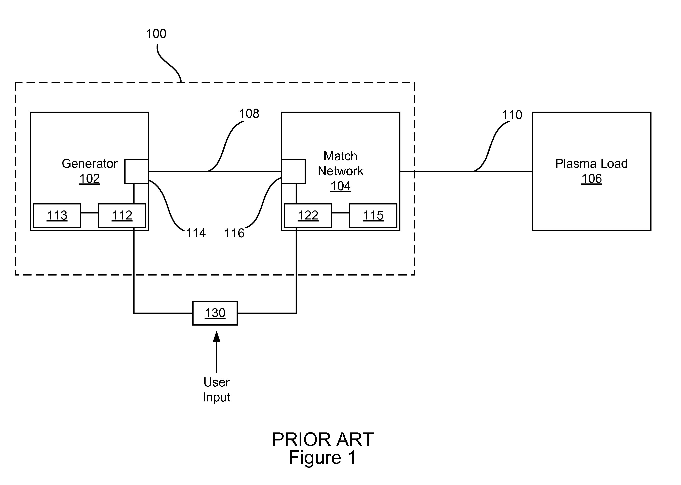
As seen, speed and accuracy are limited in traditional systems resembling that of FIG. 1.
Quality may also be hampered in the art since the power delivery system 100's inaccuracy and slow speed can lead to inconsistent power delivery.
Power quality is a particular issue in these cases since each generator and match network not only have to account for the plasma load, but also for the other generators, which are visible to each other.
In other words, the impedance matching challenge is increased where multiple generators are involved, and thus power quality is further degraded when multiple generators are used.
While the system of FIG. 1 may have been adequate in the past, it may not be adequate to provide quickly adjusting, accurate, and consistent power to nonlinear, dynamic plasma loads characteristic of new processes with more stringent requirements of accuracy and stability and short processing steps.

Method used


Image

  • System level power delivery to a plasma processing load
  • System level power delivery to a plasma processing load
  • System level power delivery to a plasma processing load

Examples


Embodiment Construction

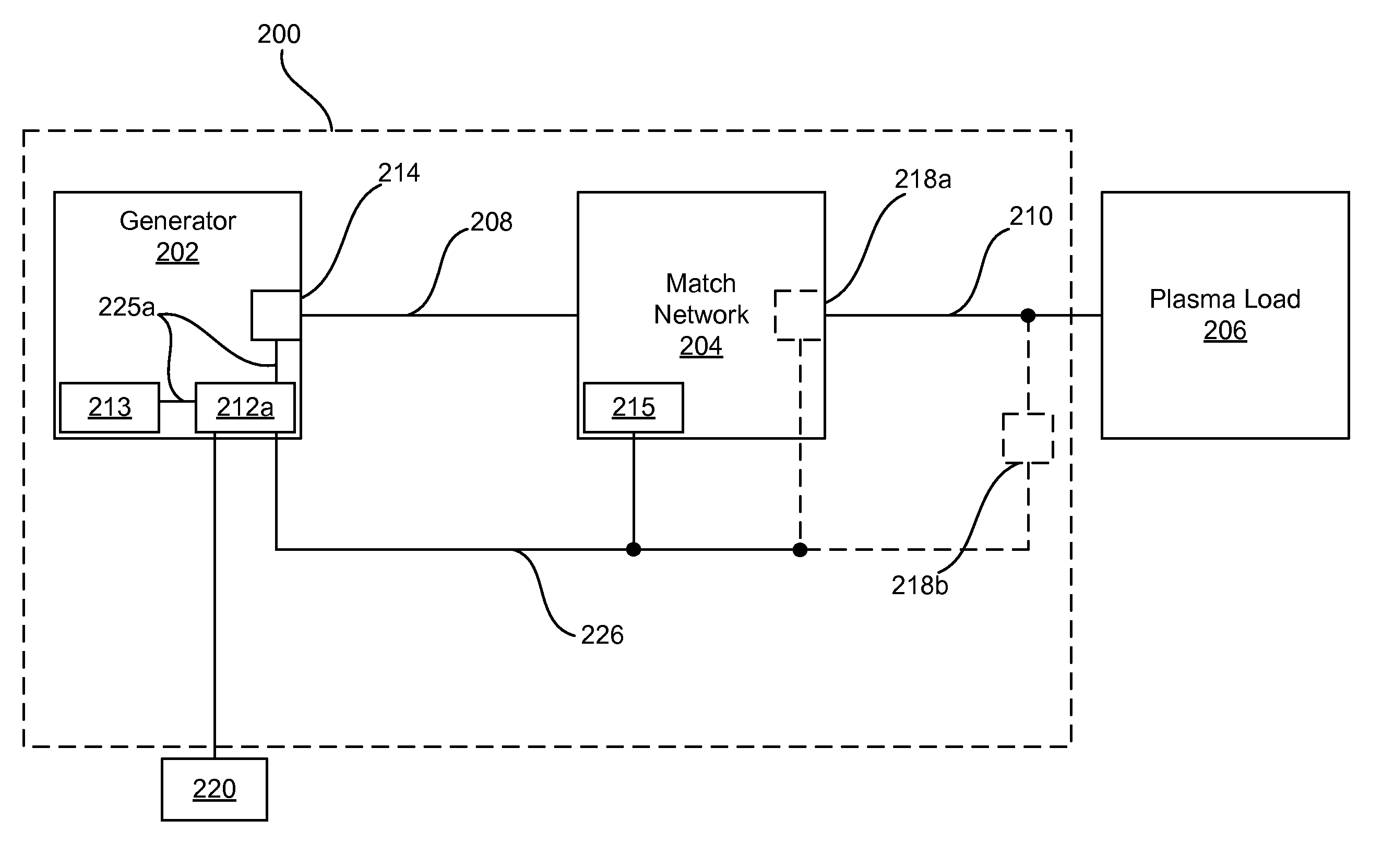
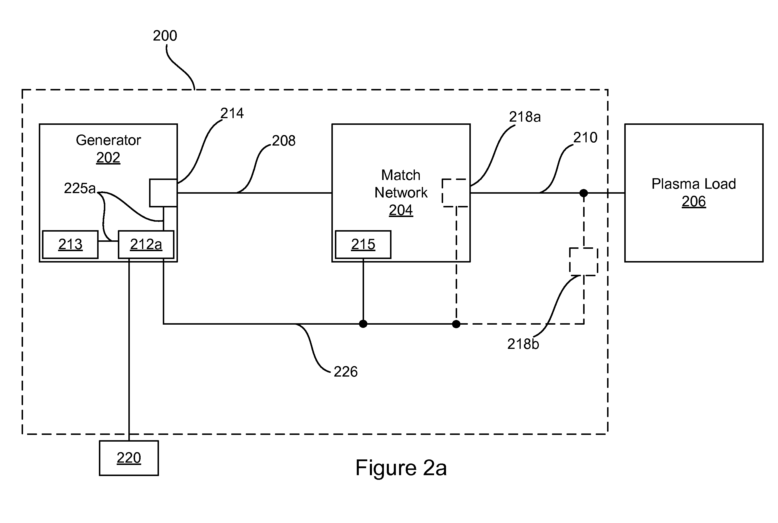
[0025]This disclosure overcomes the challenges faced in the prior art by recognizing that traditional and even cutting edge systems are still limited by their autonomous design—in particular, a generator and match network independently operated. This disclosure describes systems, methods, and apparatuses for integrating communication, measurement, and control amongst components of a power delivery system (also known as a power generation and delivery system). Some advantages of this approach include the ability to provide accurate power regulation over a wide dynamic range, faster power stabilization during transients, and decreased reflected power, for both pulsed and continuous wave (CW) power.

[0026]FIGS. 2a-2c illustrate three embodiments of a power delivery system 200. The power delivery system 200 provides power to a plasma load 206, where a match network 204 minimizes reflected power. A generator 202 power output is provided to the match network 204 via a first transmission me...


PUM


Abstract

The present disclosure discusses a power delivery system, and methods of operation, configured to monitor characteristics of a generator, a match network, and a plasma load, via one or more sensors, and control these components via a local controller in order to improve power delivery accuracy and consistency to the plasma load. Control can be based on a unified monitoring of power characteristics in the power delivery system as well as variations between components and even non-electrical characteristics such as plasma density, end point, and spectral components of plasma light emission, to name a few.

Description

PRIORITY AND CROSS REFERENCE TO RELATED APPLICATIONS[0001]This application claims the benefit of Provisional U.S. Patent Application No. 61 / 429,472 filed on Jan. 4, 2011. The details of Application No. 61 / 429,472 are incorporated by reference into the present application in their entirety and for all proper purposes.FIELD OF THE INVENTION[0002]This invention relates to maintaining consistent power delivery to a plasma processing load. More particularly it relates to systems level unification of generator(s), match network(s), sensors, and the monitoring and control of the same.BACKGROUND OF THE INVENTION[0003]The continued drive for ever shrinking features in semiconductor manufacturing poses significant challenges for tool manufacturers and process developers alike. Requirements such as higher uniformity, tighter control of critical dimensions, reduced plasma damage, thinner layers, and shorter process times, combined with the introduction of new materials demand higher sophisticat...

Claims


Application Information

Patent Timeline
IPC IPC(8): H01J7/44
CPCH01J37/32183H03H7/40H05H2242/26H05H1/40H01L21/3065
Inventor BLACKBURN, THOMAS JOELMCINTYRE, THOMASTOMASEL, FERNANDO GUSTAVO
Owner AES GLOBAL HLDG PTE LTD
Learn More