
Eureka
For R&D, Eureka makes reading and utilizing patents & technical documents easy.
Eureka AIR
Designed for self-driven R&D workflows. Generate viable solutions, solve complex R&D challenges, empower your innovation with AI.

Eureka Materials
Designed for material experts only. Revolutionize your material R&D, from search, analyze, to developing new materials.

TechResearch
Generate reliable direction feasibility study reports for your R&D in just a few steps.

TechSeek
Discover and master advanced knowledge NOW. Basics, ideas, possibilities, all at once.

TechMind
As an expert in R&D Theories, TechMind can generates customized viable solutions instantly.

TechRisk
Analyze your overall solution with one click, know your potential R&D risks in advance.

TechMonitor
Get weekly tech updates, stay abreast of the latest tech innovations and key insights.
Inverter control device, electric compressor using inverter control device, and electric equipment
- Summary
- Abstract
- Description
- Claims
- Application Information
AI Technical Summary
Benefits of technology
Problems solved by technology
Method used
Image

Examples
embodiment 1
Basic Configuration of Inverter Control Device
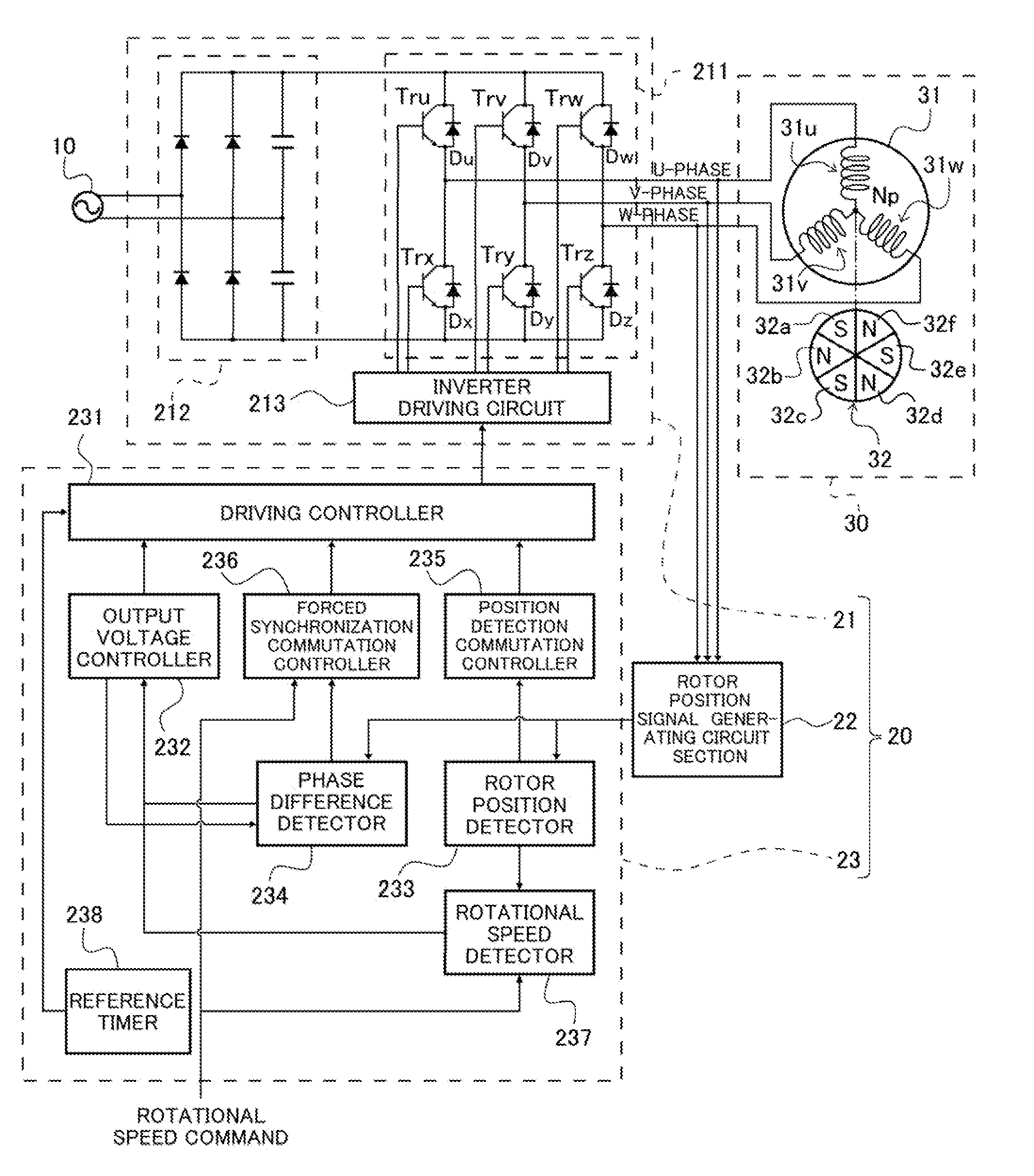
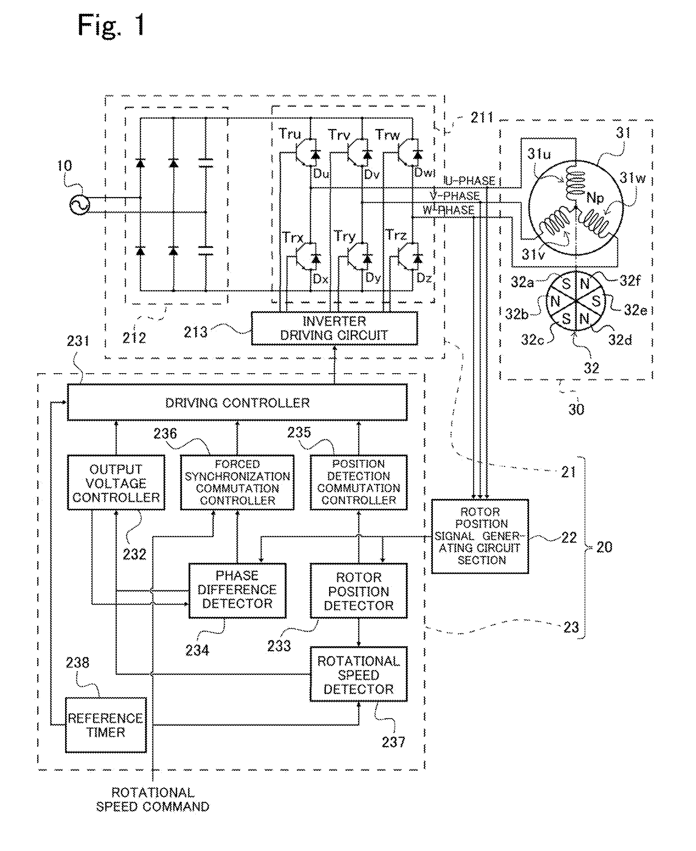
[0035]First of all, an exemplary configuration of an inverter control device of Embodiment 1 will be described with reference to FIG. 1.
[0036]Turning now to FIG. 1, an inverter control device 20 of the present embodiment is configured to control the operation of a brushless DC motor 30, and includes an inverter circuit section 21, a rotor position signal generating circuit section 22, and an inverter control section 23.
[0037]The brushless DC motor 30 (hereinafter simply referred to as DC motor 30), which is to be controlled by the inverter control device 20, is a three-phase permanent magnet synchronous motor. As shown in FIG. 1, the DC motor 30 includes a stator 31 constituted by three-phase windings and a rotor 32 including permanent magnets 32a to 32f.
[0038]The stator 31 includes a stator winding 31u corresponding to U-phase, a stator winding 31v corresponding to V-phase, and a stator winding 31w corresponding to W-phase. The rotor 3...
embodiment 2
[0119]In Embodiment 1, the driving controller 231 is capable of switching the control based on a desired condition when the forced synchronization commutation control shifts to the position detection commutation control (see step S106 in FIG. 3). In contrast, in Embodiment 2, the driving controller 231 is configured to shift from the forced synchronization commutation control to the position detection commutation control based on the rotational speed command. This configuration will be described specifically.
[0120]The inverter control device 20 of Embodiment 2 has the same configuration as that of Embodiment 1, as shown in FIG. 1, and will not be specifically in repetition. In the inverter control device 20 of the present embodiment, the output voltage controller 232 changes the output voltage control signal when a target value (rotational speed command) of a rotational speed becomes equal to or less than a preset lower limit value, when the driving controller 231 is controlling the...
embodiment 3
[0129]In Embodiment 1 or 2, the inverter control device 20 controls the operation of the DC motor 30 sensorlessly. In Embodiment 3, a description will be specifically given of an electric compressor including the inverter control device 20 of Embodiment 1 or 2 and the DC motor 30 controlled by the inverter control device 20, and a refrigerator including the electric compressor.
[0130][Exemplary Configuration of Electric Compressor]
[0131]The inverter control device 20 of Embodiment 1 or 2 is suitably applied to the electric compressor included in the refrigerator. This electric compressor will be described with reference to FIG. 8.A.
[0132]Referring to FIG. 8A, the electric compressor 40 includes the inverter circuit section 21 of Embodiment 1 or 2, the inverter control section 23 of Embodiment 1 or 2, the DC motor 30 of Embodiment 1 or 2, and a compression mechanism 41. The inverter control device 20 includes the inverter circuit section 21, the inverter control section 23, and the ro...
PUM
 Abstract
Description
Claims
Application Information
 - R&D Engineer
- R&D Manager
- IP Professional
- Industry Leading Data Capabilities
- Powerful AI technology
- Patent DNA Extraction
Browse by: Latest US Patents, China's latest patents, Technical Efficacy Thesaurus, Application Domain, Technology Topic, Popular Technical Reports.
© 2024 PatSnap. All rights reserved.Legal|Privacy policy|Modern Slavery Act Transparency Statement|Sitemap|About US| Contact US: help@patsnap.com