Monitoring system for an energy storage cell

a monitoring system and energy storage cell technology, applied in the field of monitoring systems, can solve problems such as system failure, leakage current, corrosion, etc., and achieve the effect of reducing costs and increasing the safety of the battery system

Active Publication Date: 2013-01-03
SAMSUNG SDI CO LTD
View PDF26 Cites 26 Cited by
  • Summary
  • Abstract
  • Description
  • Claims
  • Application Information

AI Technical Summary

Benefits of technology

[0014]It is, therefore, an object of the invention to increase the safety of the battery system whilst simultaneously minimizing the costs relating to the material and the assembly process without adversely affecting the monitoring functions.

Problems solved by technology

However, if only one of the thin voltage sampling conductors breaks, then the system must not be operated.
Condensation water and contamination can cause leakage currents and corrosion to occur at this site in the CSC.
Short circuits in the voltage sampling conductors and in the CSC are a source of a fault that is extremely difficult to overcome in conventional systems.
It is difficult using conventional protective measures to protect the numerous voltage sampling conductors.
Short circuits can be caused a) by mechanical abrasion or fracture, b) by foreign bodies, c) by lack of attention during the assembly process or during maintenance work and d) as a subsequent fault if there is a leakage of cooling fluid.
The many parts that conduct voltage to ground also increase the probability of a ground fault and the risk of an electric shock for people working on the battery system.
In addition, it is extremely difficult in the case of Li-ion batteries to detect lithium deposits (lithium dendrites) on an overloaded anode.
In the worst case scenario, the lithium dendrites can cause damage to a separator film and as a further consequence lead to an internal short circuit in the cell.

Method used


Image

  • Monitoring system for an energy storage cell
  • Monitoring system for an energy storage cell

Examples


Embodiment Construction

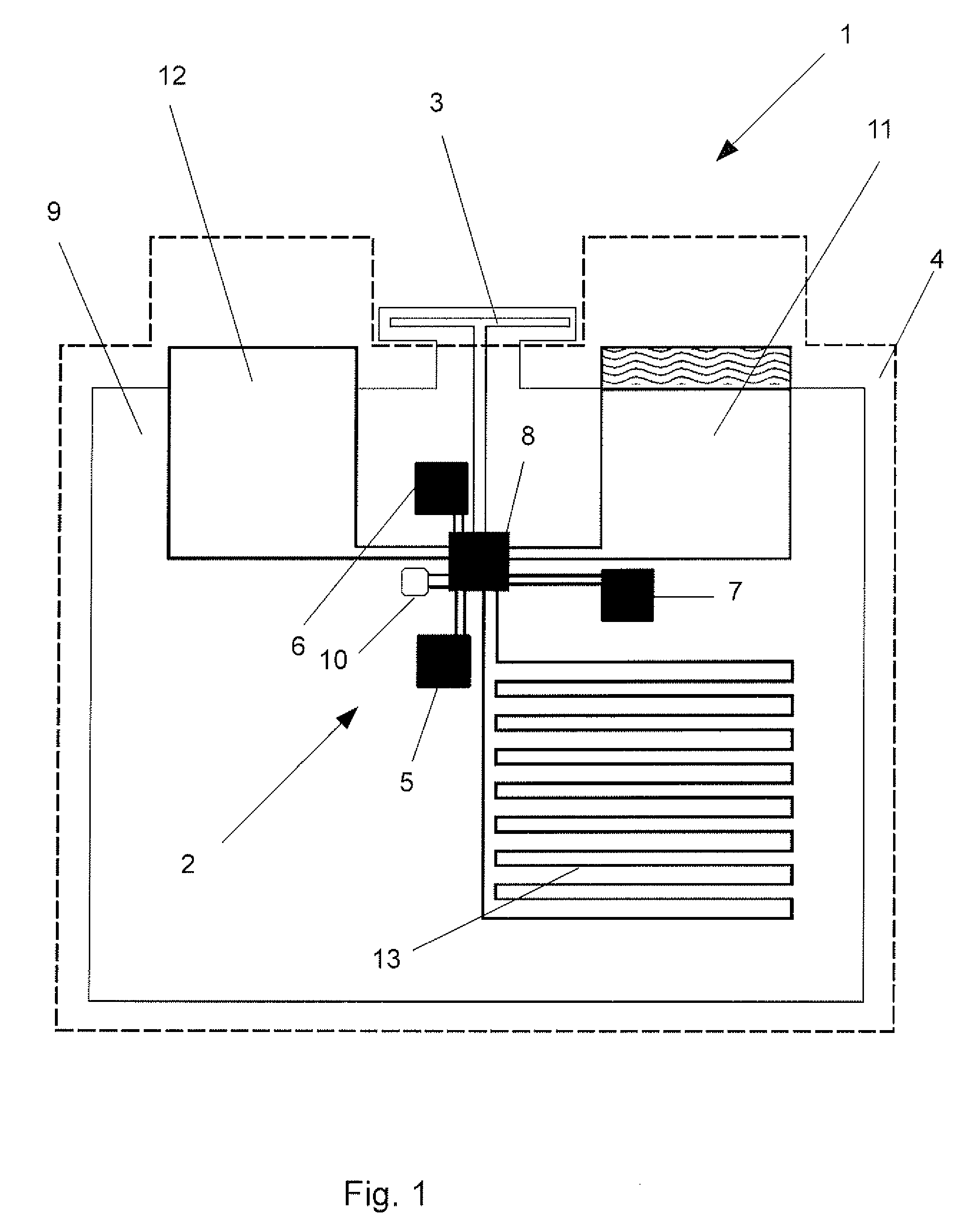
[0029]It is stated by way of introduction that the present invention is not limited to the use of electrochemical energy storage cells (e.g., Lithium ion cells), but rather can also be used with other types of energy storage devices or energy storage cells, for example capacitors and in particular double-layer capacitors.

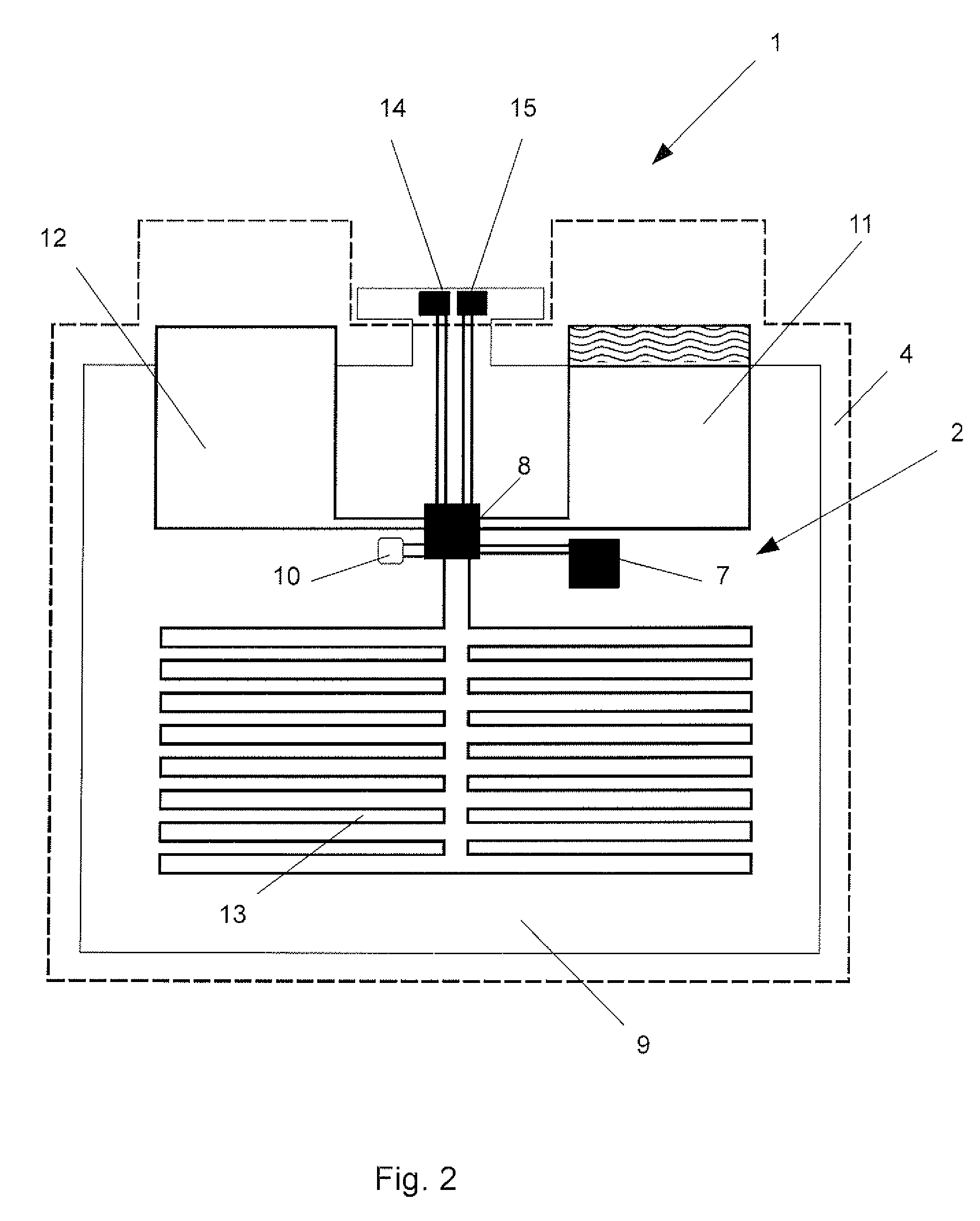
[0030]As illustrated in FIG. 1, in the case of an energy storage cell 1 in accordance with the invention, the CSCs usually used in the prior art are replaced by electronics 2 integrated directly in the energy storage cell 1, which electronics are designated hereinunder as an Integrated Cell Circuit or ICC in short. A plurality of energy storage cells 1 in accordance with the invention, as illustrated in FIG. 1 or FIG. 2, can be combined to form a battery system. Each energy storage cell 1 can communicate, preferably in a wireless manner, by means of its installed

[0031]ICC 2 with a BMU of the battery system (the BMU is not illustrated here in detail). For this purpos...


PUM


Abstract

A monitoring system for monitoring the state of an energy storage cell for storing electrical energy, in particular, an electrochemical energy storage cell or an energy storage cell having at least one capacitor. Integrated electronics for monitoring the state of the energy storage cell are arranged in the energy storage cell, the integrated electronics having a transmitting/receiving unit for wireless data exchange with a battery control system arranged outside the energy storage cell. Alternatively, the integrated electronics are connected to a transmitting/receiving unit for wireless data exchange with a battery control system arranged outside the energy storage cell.

Description

CROSS-REFERENCE TO RELATED APPLICATIONS[0001]The present application is a National Stage Application of PCT International Application No. PCT / EP2011 / 053717 (filed on Mar. 11, 2011), under 35 U.S.C. §371, which claims priority to German Patent Application No. 10 2010 048 379.6 (filed on Oct. 13, 2010) and U.S. Provisional Patent Application No. 61 / 316,946 (filed on Mar. 24, 2010), which are each hereby incorporated by reference in their respective entiretiesFIELD OF THE INVENTION[0002]The invention relates to a monitoring system for monitoring the state of an energy storage cell for storing electrical energy, in particular an electrochemical energy storage cell or an energy storage cell comprising at least one capacitor.[0003]The invention further relates to a battery system having a plurality of energy storage cells and a central battery control system for controlling and monitoring the energy storage cells.[0004]Conventional battery systems are usually sub-divided into a plurality ...

Claims


Application Information

Patent Timeline
Patent Type & Authority Applications(United States)
IPC IPC(8): G01R31/36
CPCG01R31/362H01M10/4257H01M10/486H01M10/48H01M10/484H01M10/4264G01R31/3835Y02E60/10
Inventor GOLUBKOV, ANDREJ
Owner SAMSUNG SDI CO LTD
Why Eureka
Try Eureka