
Method and apparatus for detection of catheter location for intravenous access

a catheter location and catheter technology, applied in the field of medical imaging, can solve the problems of care costs, real costs associated with iv care, few techniques for assisting nurses and clinicians, etc., and achieve the effect of reducing the light being detected

Active Publication Date: 2013-01-03
CHRISTIE MEDICAL HLDG
View PDF3 Cites 24 Cited by
  • Summary
  • Abstract
  • Description
  • Claims
  • Application Information

AI Technical Summary

Benefits of technology

The present invention provides a system for detecting cannulation of a catheter using a needle, light source, camera, and projector. The system can illuminate patient's skin and detect the reflected light, which is absorbed by hemoglobin in the blood. As the needle is pushed into the patient's skin, the tip will continue to be visible to the camera until a successful cannulation event has occurred. This helps the clinician to position the needle accurately. The system can also project an image of the needle onto the patient's skin for easier positioning. The detection of cannulation is possible using different wavelengths of light or alternating pulses of light for illuminating the skin and the needle tip. The technical effects of this invention include improved accuracy in catheter insertion and reduced risk of complications.

Problems solved by technology

There are very few techniques for assisting nurses and clinicians in verifying a positive cannulation of a vein.
Aside from the increased pain and anxiety experienced by patients, there are real costs associated with IV care.
Patient throughput, nurse time, consumables, and increased infection rates all contribute to increased medical care costs for hospitals and governments.
Although the VeinViewer® system has been widely adopted by hospitals, its application has been somewhat limited by the fact that it cannot detect a successful cannulation event.

Method used


Image

  • Method and apparatus for detection of catheter location for intravenous access
  • Method and apparatus for detection of catheter location for intravenous access
  • Method and apparatus for detection of catheter location for intravenous access

Examples


first embodiment

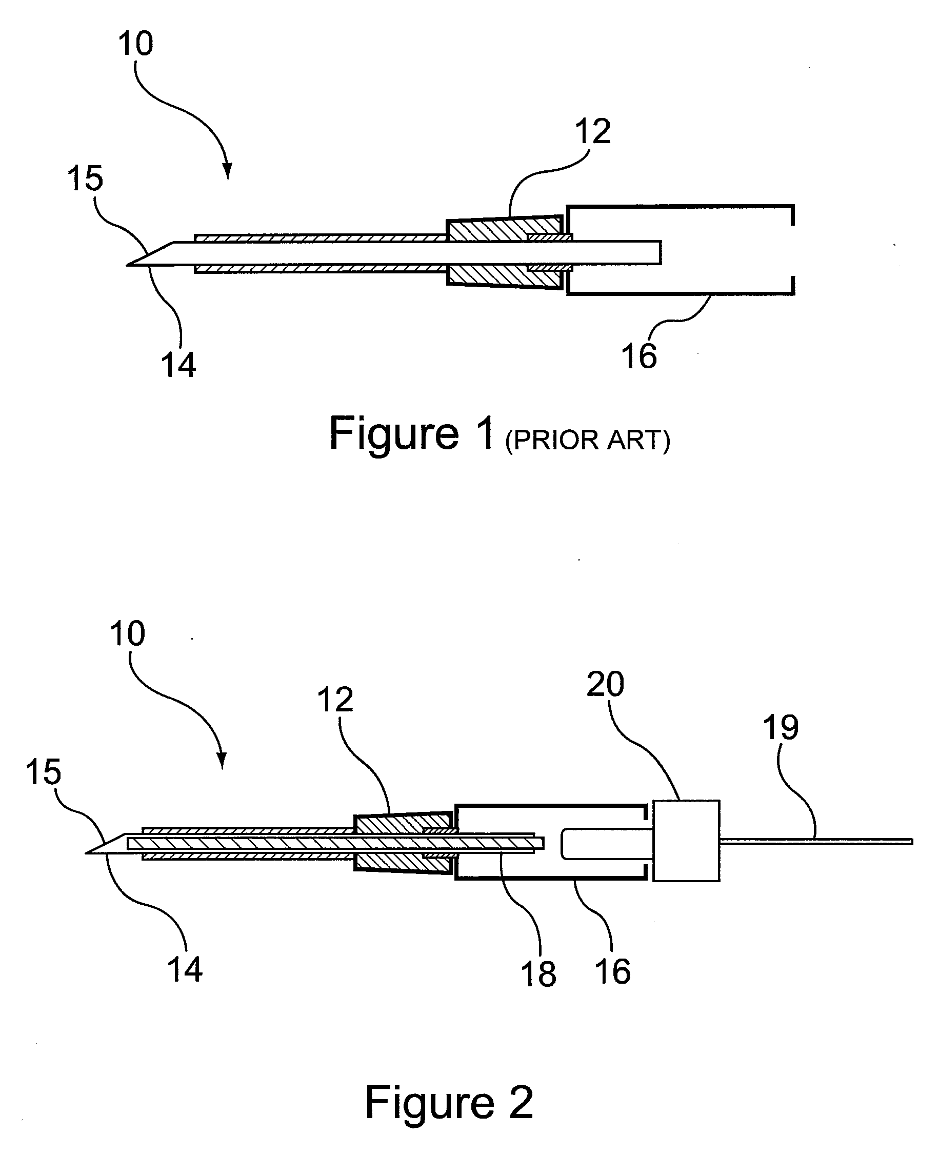
[0030] as shown in FIG. 2, the IV catheter 10 of FIG. 1 can be illuminated via a fibre optic light guide 18 disposed within the needle 14. The light guide is illuminated from the needle housing 16 and propagates light to the needle tip 15. A source of illumination or illuminator (discussed in greater detail with reference to FIGS. 6 and 7) generates light at a wavelength chosen to be transparent to tissue but readily absorbed by haemoglobin. Wavelengths in the range of 650-1100 nm are suitable. The illuminator can be a laser, LED or other suitable light source, and can be disposed within housing 16 or can be connected to the housing from a remote location via optical fibre 19 and a light source coupler 20. The coupler 20 ensures accurate alignment between the light-generating tip of the optical fibre 19 and the light guide 18. The use of a remote illuminator also eliminates any obtrusion around the catheter, for ease of insertion.

second embodiment

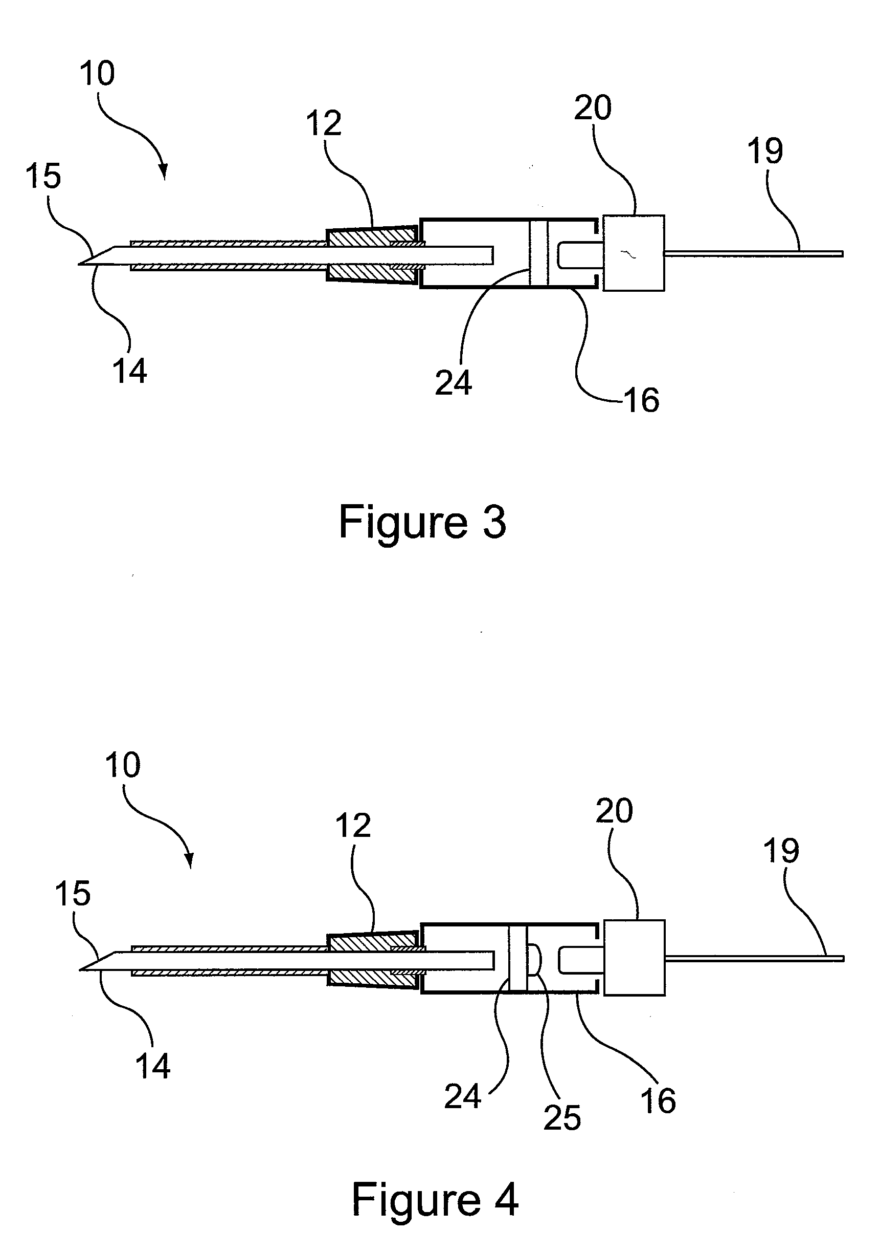
[0031]In a second embodiment, shown in FIG. 3, the hollow needle 14 is used as a light guide such that no fibre 18 is required. The light source coupler 20 mounts directly to the needle housing 16 and self-aligns with the back of the needle 14. Light propagates down the needle shaft and is reflected out at the sharp side of the needle 14.

[0032]A window 24 is molded into the plastic needle housing 16. The purpose of the window 24 is to create a blood flashback chamber that can be used as a visual detector for cannulation while preventing blood from contaminating the light source coupler 20.

third embodiment

[0033]In a third embodiment, illustrated in FIG. 4, a plano-convex lens 25 is provided having a suitable radius to match the fibre numerical aperture output of optical fibre 19 for enhanced optical coupling into the needle 14. The lens 25 can be molded into the optical window 24 as part of the manufacturing process. The lens 25 focuses the diverging light emitted from the optical fibre 19 to a point at the opening in the end of the needle 14. This ensures maximum light coupling and light transmission to the needle tip 15.

[0034]According to a further embodiment, illustrated in FIG. 5, a self-centering mechanism 26 is provided in the walls of the needle housing 16 to ensure the light source coupler 20 self centers to the optical window 24 and lens 25. This can be accomplished using a slight taper to the needle housing walls that matches the light source coupler. In this way, the coupler self centers but can also be “locked” in place by friction. Alternatively, a quarter-turn thread (n...


PUM


Abstract

A system is set forth for detection of catheter location for intravenous access, comprising a catheter having a light source for illuminating a needle tip thereof; and an infrared detector and image projector for simultaneously detecting image vasculature and the location of the needle tip below the surface of the skin and in response projecting an image onto the skin to reveal the location of the needle tip relative to the vasculature.

Description

BACKGROUND OF THE INVENTION[0001]1. Field of the Invention[0002]The present invention is directed to medical imaging and more particularly to a method and apparatus for detection of catheter location for intravenous access.[0003]2. Description of the Related Art[0004]Intravenous (IV) catheters are used to access veins for blood draw, and for fluid delivery. There are very few techniques for assisting nurses and clinicians in verifying a positive cannulation of a vein. The standard technique for peripheral IV access involves using a tourniquet to engorge veins, followed by palpation to identify a suitable vein and finally insertion of the catheter needle. Clinicians must rely on “feel” when inserting the needle into a vein and on observing blood flashback to ascertain when the catheter has successfully cannulated the vein. Statistics indicate that this trial-and-error process requires an average of 2.4 attempts and up to 20 min for a clinician to successfully cannulate a vein. Aside ...

Claims


Application Information

Patent Timeline
IPC IPC(8): A61M5/42
CPCA61B5/0059A61B5/489A61B5/06A61B2090/366A61M25/0606A61M2025/0166A61M5/427A61B8/0841A61B17/3403
Inventor PINHO, GEORGE P.WAGNER, ROBERT BENJAMIN
Owner CHRISTIE MEDICAL HLDG
Learn More