Control system for doubly-fed induction machine

a control system and induction machine technology, applied in the direction of motor control for motor oscillation damping, electric generator control, dynamo-electric converter control, etc., can solve the problems of limiting the transmission of generated power, permanent damage, and no clear means of damping the resonance in the paper

Inactive Publication Date: 2013-01-10
ABB OY
View PDF2 Cites 18 Cited by
  • Summary
  • Abstract
  • Description
  • Claims
  • Application Information

AI Technical Summary

Benefits of technology

[0009]A method is disclosed of controlling a doubly-fed induction machine by a frequency converter including a rotor side converter (INU) connected to a rotor circuit of the doubly-fed induction machine (DFIG) and having a control system with rotor flux as a feedback variable, a grid side converter (ISU) connected to an AC power network, and a direct voltage intermediate circuit (DC) connected between the rotor side converter (INU) and the grid side converter (ISU), forming a rotor flux reference (ψr,ref), forming a damping signal (ψref,D), summing the damping signal and the rotor flux reference for obtaining a modified rotor flux reference (ψref), and feeding the modified rotor flux reference to a controller of the rotor side converter (INU) for damping sub-synchronous resonances.
[0010]An arrangement for controllin

Problems solved by technology

The long line can have a considerable inductance that can limit transmission of the generated power.
This series compensation of the inductance can have the drawback that the capacitor with the inductances of the line and the supplying network form a resonance circuit that has a resonance frequency lower than the nominal frequency (50 or 60 Hz) of the grid.
Excitation of this sub-synchronous resonance can cause a rapid variation of the voltage magnitude and phase, which can cause mechanic

Method used


Image

  • Control system for doubly-fed induction machine
  • Control system for doubly-fed induction machine
  • Control system for doubly-fed induction machine

Examples


Embodiment Construction

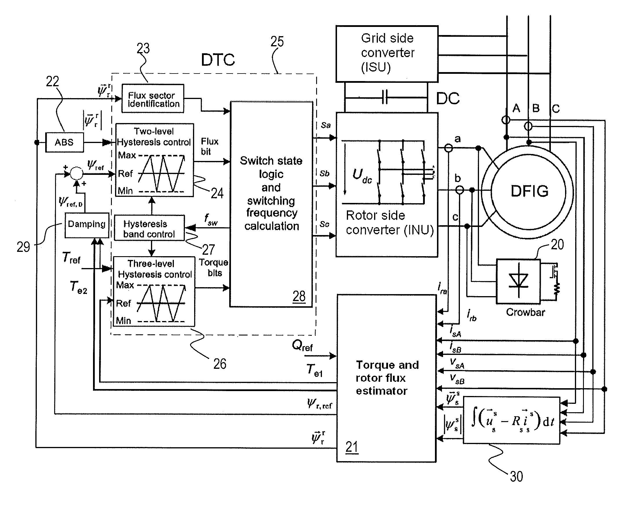
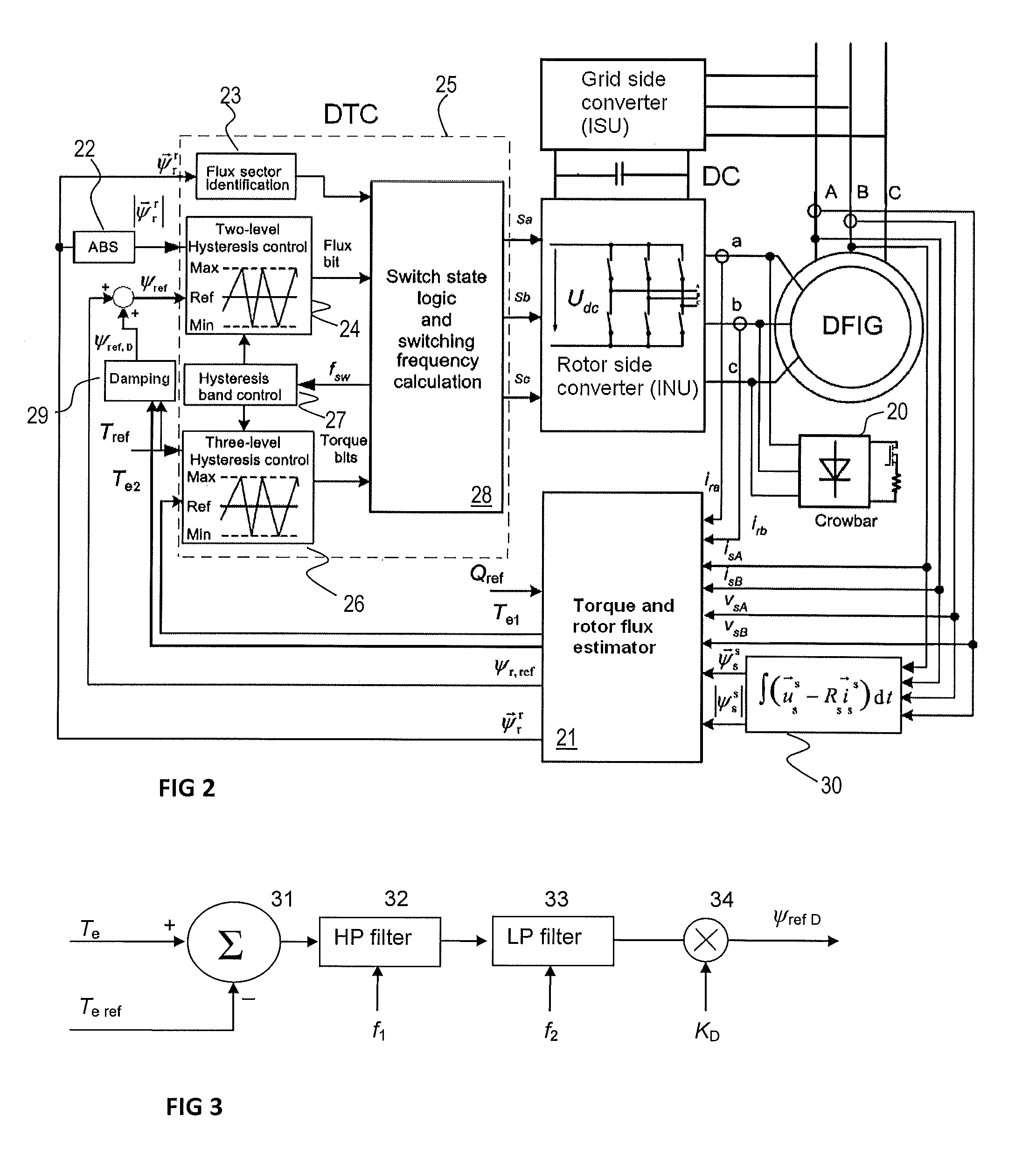
[0017]Exemplary embodiments of the present disclosure provide a method and an arrangement for implementing the method so as to solve the above issues in connection with doubly-fed induction generators.

[0018]Exemplary embodiments of the disclosure are based on the idea of modifying a rotor flux reference in the control system controlling the rotor flux. The modified rotor flux reference can be obtained by summing a damping signal to a signal that can be used as a rotor flux reference. The modified rotor flux signal is then used in the control as the reference signal.

[0019]The damping signal can be formed on the basis of an estimated machine torque or another signal having similar characteristics.

[0020]An advantage of the method and arrangement is that it can damp effectively sub-synchronous oscillations so that the network can be used securely and the production of power can be stable.

[0021]A further advantage is that it can be used throughout the whole speed range for stabilizing th...


PUM


Abstract

A method and arrangement for controlling a doubly-fed induction machine by a frequency converter including a rotor side converter (INU) connected to a rotor circuit of a doubly-fed induction machine (DFIG) and having a control system with rotor flux as a feedback variable, a grid side converter (ISU) connected to an AC power network, and a direct voltage intermediate circuit (DC) connected between the rotor side converter (INU) and the grid side converter (ISU). The method includes forming a rotor flux reference (ψr,ref), forming a damping signal (ψref,D), summing the damping signal and the rotor flux reference for obtaining a modified rotor flux reference (ψref), and feeding the modified rotor flux reference to a controller of the rotor side converter (INU) for damping sub-synchronous resonances.

Description

RELATED APPLICATION(S)[0001]This application claims priority under 35 U.S.C. §119 to European Patent Application No. 11173259.0 filed in Europe on Jul. 8, 2011, the entire content of which is hereby incorporated by reference in its entirety.FIELD[0002]The present disclosure relates to doubly-fed machines, for example, to damping of sub-harmonic oscillations of an AC power network by control of doubly-fed machines.BACKGROUND INFORMATION[0003]Doubly-fed induction machines can be used in various generator and motor drives. One such electric machine drive including converters can be a doubly-fed slip-ring generator configuration whose rotor circuit includes two converters having a direct voltage intermediate circuit therebetween. One converter can be situated electrically between the direct voltage intermediate circuit and a rotor while the other converter can be situated electrically between the direct voltage intermediate circuit and an electrical network to be supplied.[0004]Such dou...

Claims


Application Information

Patent Timeline
IPC IPC(8): H02P9/42
CPCH02P9/007H02P23/04B26D7/015B31D1/0043B26F1/14B26F1/22B26F1/36
Inventor NIIRANEN, JOUKOSEMAN, SLAVOMIRVIRTANEN, REIJO
Owner ABB OY
Why Eureka
Try Eureka