
Magnetic resonance imaging apparatus and control device of a magnetic resonance imaging apparatus

a magnetic resonance imaging and control device technology, applied in the field of magnetic resonance imaging, can solve the problems of insufficient ability to endure, difficulty in accurately estimating the application limits of a gradient magnetic field generation system in terms of electric power depending on an imaging sequence, and various limitations of the gradient magnetic field generation system

Active Publication Date: 2013-01-10
TOSHIBA MEDICAL SYST CORP
View PDF5 Cites 32 Cited by
  • Summary
  • Abstract
  • Description
  • Claims
  • Application Information

AI Technical Summary

Benefits of technology

The patent text describes the desire for technology to accurately determine if an MRI scan can be successfully performed based on the electric load on the MRI machine. It also describes the need for accurate information on the actual gradient magnetic field waveform to perform regridding or parameter correction processing with a high degree of accuracy.

Problems solved by technology

A gradient magnetic field generation system has various limitations in terms of the total upper limit of electric power, the respective upper limits of electric power in each channel and the like, and does not have enough ability to endure the maximum electric current in every channel (X axis direction, Y axis direction and Z axis direction) concurrently.
However, in conventional technology, it is difficult to precisely estimate application limits of a gradient magnetic field generation system in terms of electric power depending on an imaging sequence.
However, “a waveform of gradient magnetic field current” and “a waveform of a gradient magnetic field actually generated by this gradient magnetic field current” do not necessarily accord with each other.

Method used


Image

  • Magnetic resonance imaging apparatus and control device of a magnetic resonance imaging apparatus
  • Magnetic resonance imaging apparatus and control device of a magnetic resonance imaging apparatus
  • Magnetic resonance imaging apparatus and control device of a magnetic resonance imaging apparatus

Examples


first embodiment

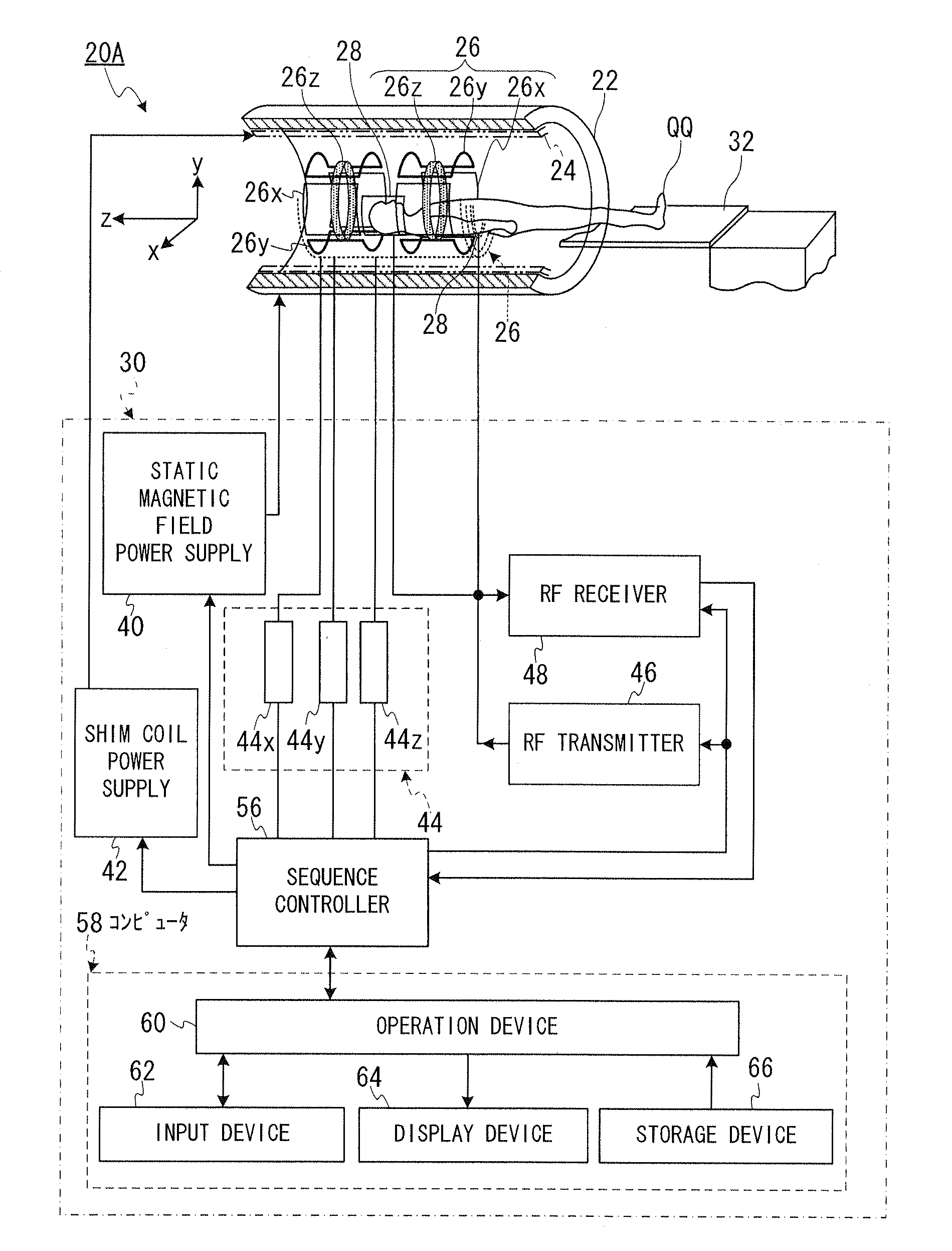
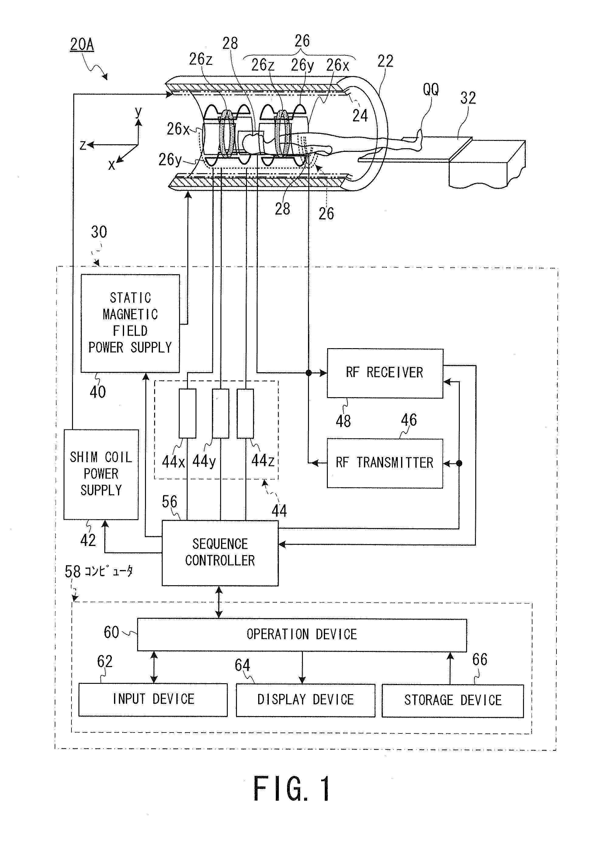
[0071]FIG. 1 is a block diagram showing general structure of the MRI apparatus 20A according to the first embodiment.

[0072]As shown in FIG. 1, the MRI apparatus 20A includes a cylinder-shaped static magnetic field magnet 22 for generating a static magnetic field, a cylinder-shaped shim coil 24 coaxially-arranged inside the static magnetic field magnet 22, a gradient magnetic field coil 26, RF coils 28, a control device 30, and a bed 32 for placing an object (e.g. a patient) QQ on it.

[0073]Here, as one example, an apparatus coordinate system, whose X axis, a Y axis and a Z axis are perpendicular to each other, is defined as follows. Firstly, the direction of an axis of the static magnetic field magnet 22 and the shim coil 24 is aligned with the direction which is perpendicular to the vertical direction, and the direction of the axis of the static magnetic field magnet 22 and the shim coil 24 is defined as the Z axis direction.

[0074]Additionally, it is assumed that the vertical direct...

second embodiment

[0425]In the second embodiment, the regridding processing will be described in further detail. The second to fifth embodiments are the same as the first embodiment in that the gradient magnetic field waveform is calculated with high accuracy. The entire configuration of the hardware of an MRI apparatus 20B according to the second to fifth embodiments is the same as that of the MRI apparatus 20A according to the first embodiment described above with reference to FIG. 1, and therefore, illustration of the entire configuration thereof is omitted.

[0426]The MRI apparatus 20B according to the second to fifth embodiments differs from the MRI apparatus 20A according to the first embodiment in functionality of the computer. In the following, the computer and the operation device are renumbered as 58′ and 60′, respectively, and differences from the first embodiment will be mainly described.

[0427]FIG. 18 is a functional block diagram showing the computer 58′ in the MRI apparatus 20B according ...

third embodiment

[0527]The third embodiment is a modification of the second embodiment.

[0528]FIG. 26 is a flowchart showing an operation of the MRI apparatus 20B according to the third embodiment. The third embodiment differs from the second embodiment in that a prescan for verifying the circuit constants of the equivalent circuit (in Steps S44 to S49) is additionally provided. In the following, according to the step numbers shown in FIG. 26, the operation of the MRI apparatus 20B according to the third embodiment will be described.

[0529][Steps S41 to S43] The processing in these steps is the same as those in Steps S21 to S23 in the second embodiment. Then, the process proceeds to Step S44.

[0530][Steps S44 to S48] In Steps S44 to S48, image data of an evaluation image are generated as a part of the prescan. The specific processing in Steps S44 to S48 is basically the same as those in Steps S24 to S28 of the main scan in the second embodiment, respectively, but differ from them in that the generated ...


PUM


Abstract

According to one embodiment, a control device (30) of a magnetic resonance imaging apparatus (20A) includes a condition setting unit (100) and a judging unit (102). The condition setting unit sets an imaging sequence performed by the magnetic resonance imaging apparatus based on conditions of the imaging sequence. The judging unit calculates a value of electric current supplied to a gradient magnetic field coil (26) of the magnetic resonance imaging apparatus based on the conditions of the imaging sequence, calculates a value of voltage applied to the gradient magnetic field coil based on “a mutual inductance by which the gradient magnetic field coil causes mutual induction” so that electric current flowing the gradient magnetic field coil becomes equal to the value of electric current calculated, and judges whether the imaging sequence is practicable or not based on the value of voltage.

Description

CROSS-REFERENCE TO RELATED APPLICATIONS[0001]This application is a Continuation application of No. PCT / JP2012 / 64927, filed on Jun. 11, 2012, and the PCT application is based upon and claims the benefit of priority from Japanese Patent Application No. 2011-131388, filed on Jun. 13, 2011 and Japanese Patent Application No. 2011-131067 filed on Jun. 13, 2011, the entire contents of which are incorporated herein by reference.BACKGROUND OF THE INVENTION[0002]1. Field of the Invention[0003]Embodiments described herein relate generally to magnetic resonance imaging.[0004]2. Description of the Related Art[0005]MRI is an imaging method which magnetically excites nuclear spin of an object (a patient) set in a static magnetic field with an RF pulse having the Larmor frequency and reconstructs an image based on MR signals generated due to the excitation. The aforementioned MRI means magnetic resonance imaging, the RF pulse means a radio frequency pulse, and the MR signal means a nuclear magneti...

Claims


Application Information

Patent Timeline
IPC IPC(8): G01R33/48
CPCG01R33/3852G01R33/56545G01R33/54G01R33/56572G01R33/4818G01R33/56554
Inventor HORI, MASASHIMIURA, MOTOHIROKUSAHARA, HIROSHIMACHII, YUTAKAKASSAI, YOSHIMORI
Owner TOSHIBA MEDICAL SYST CORP
Learn More