Current sensor

a current sensor and sensor technology, applied in the direction of resistance/reactance/impedence, instruments, measurement devices, etc., can solve the problems of not automatically compensating errors, difficult to accurately measure the flow of electricity over a wide dynamic range, and the physical size of the sense resistor b>2/b> can thus get to be a problem, so as to reduce the waste of energy in the sensing element

Inactive Publication Date: 2013-01-10
SENDYNE
View PDF4 Cites 37 Cited by
  • Summary
  • Abstract
  • Description
  • Claims
  • Application Information

AI Technical Summary

Benefits of technology

[0043]This circuit and the algorithm empower the creation of a current sensor that is accurate at much larger range of measured currents than in the prior art; it provides several-orders-of-magnitude dynamic range improvement. Compared with the prior-art implementations, the current invention reduces the waste of energy in the sensing element to near zero. The energy consumption of the circuit itself can be reduced to near zero levels under conditions of low reporting rates for the measured current and / or accumulated charge. Due to very low measurement offset for the DC current, an accumulated charge value is quite accurate, even under conditions of a load current that is many times smaller than the maximum rated load current.

Problems solved by technology

It is not easy to measure the flow of electricity accurately over a wide dynamic range while dissipating very little waste heat.
It is not uncommon for a DC-supplied system to spend most of its time operating at a very low power level, and to consume the full-rated energy only for relatively brief intervals.
But any non-identical temperature distributions as between the two paths can give rise to errors which are not automatically compensated by the use of differential sensing.
The physical size of the sense resistor 2 can thus get to be a problem, as can be the need to providing adequate cooling of the sense resistor.
The voltage signal in the Hall-effect device is linearly proportional to both the supply current and the magnetic field, within limitations of power dissipation resulting from the supply current, and some additional anomalous effects.
This means that there is always some latency between a current event of interest and the detection of such an event after the averaging or filtering has taken place.
A further potential difficulty with such magnetically coupled measurements (particularly where a DC current is converted to AC for purposes of Hall-effect sensing) is that during the zero crossings of the excitation voltage (that is, near the zero values for the sine-wave excitation), the Hall-effect device is altogether insensitive to the magnetic field, and simply discards any information for the duration of the zero-crossing transitions.
These factors make the Hall effect sensing less than ideal, particularly for a battery-powered system.
For the MR-effect approaches, the notably worst performance is in respect to the zero-current offset for the MR-effect based measurements.

Method used


Image

  • Current sensor
  • Current sensor
  • Current sensor

Examples


Embodiment Construction

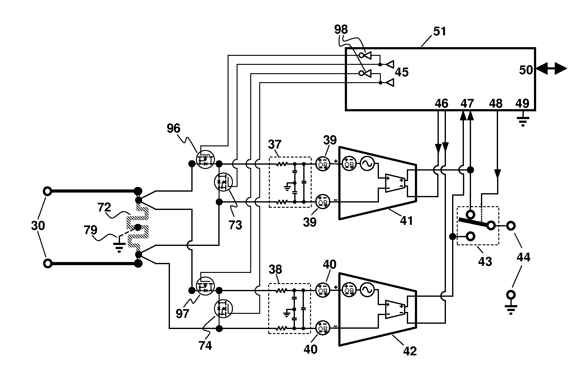
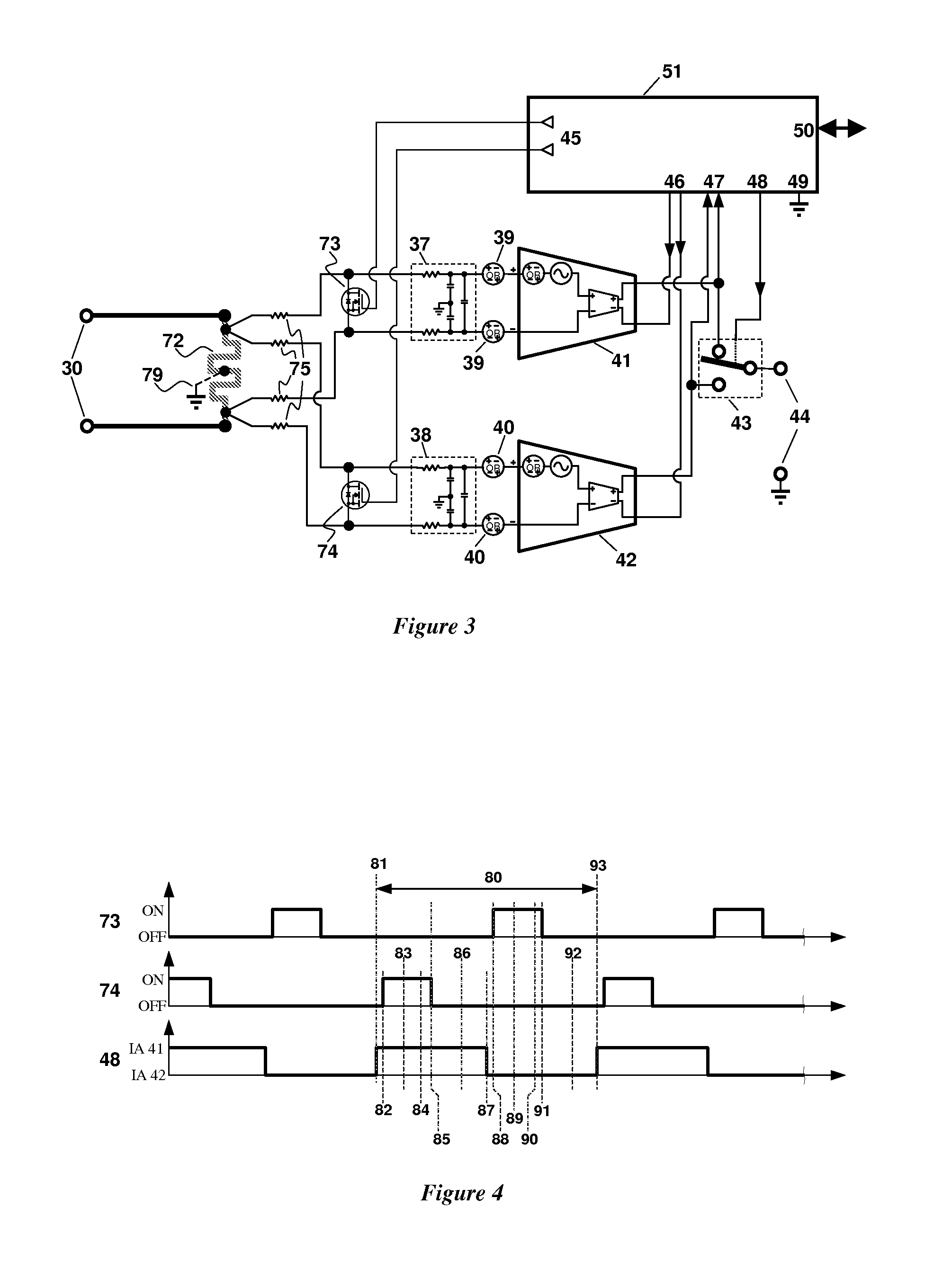
[0057]One current sensor according to the invention is shown in FIG. 3. There is a current shunt 72 providing a voltage signal proportional to the current flowing in the shunt 72 to resistors 75, which are in turn connected to field effect transistor (FET) switches 73 / 74. Further, current sense signals pass via RFI filters 37 and 38, and then get amplified by instrumentation amplifiers (IAs) 41 and 42. An analog selector switch 43 delivers the signal to output terminals 44; this signal can be either the output from IA 41, or IA 42.

[0058]Under control of the circuit 51, and via FET Drivers 45, the FETs 73 / 74 are turned either fully on or off, as required for the execution of the Algorithm detailed in FIG. 4.

[0059]The action of FETs 73 / 74 can short-circuit the signal voltage input to RFI filters 37 / 38; offset voltage errors associated with the RFI filters and the whole amplification chain 37 / 39 / 41 or 38 / 40 / 42 can then be calibrated out.

[0060]At any point in time, there will be at leas...


PUM


Abstract

An apparatus and method make use of a single shunt and two or more instrumentation amplifiers, switchably measuring voltages at the shunt. This permits current measurement. At times each instrumentation amplifier has its input shorted, which permits zeroing out many sources of offset in the signal path of that amplifier. Dynamic range is several orders of magnitude better than known current measurement approaches, permitting coulometry.

Description

BACKGROUND[0001]It is not easy to measure the flow of electricity accurately over a wide dynamic range while dissipating very little waste heat.[0002]Whenever electrical energy is used, it is desirable to measure the quantity of energy used, both per unit of time (e.g. power), and over a specific amount of time (for example, energy used per month). In a residential environment, an electric power meter is a familiar fixture; it allows the power-providing companies to charge their customers for the energy used.[0003]In the most basic terms, the instantaneous power is a product of the voltage applied to, and the current flowing through, the load. An integration of this product (power) over a specific time interval yields the total consumption of the electrical energy within that time interval.[0004]Accurate measurement of the load current is thus an important part of the apparatus that measure the consumption of electrical energy.[0005]It will be helpful to review the present state of ...

Claims


Application Information

Patent Timeline
Patent Type & Authority Applications(United States)
IPC IPC(8): G01R19/00
CPCG01R1/203G01R19/0023G01R15/146G01R29/24G01R35/005G01R19/0092G01R1/30
Inventor MARTEN, VICTOR
Owner SENDYNE
Why Eureka
Try Eureka