Spin-torque oscillator (STO) with magnetically damped free layer

Active Publication Date: 2013-01-10
WESTERN DIGITAL TECH INC
View PDF2 Cites 15 Cited by
  • Summary
  • Abstract
  • Description
  • Claims
  • Application Information

AI Technical Summary

Benefits of technology

[0009]The invention relates to a spin-torque oscillator (STO), such as a STO magnetic field sensor, with increased magnetic damping of the oscillating free layer to thereby increase the critical current. The Gilbert magnetic damping parameter (α) from the Landau-Lifshitz-Gilbert-Slonczewski equation should be at least 0.05, and preferably greater than 0.05. In one embodiment the free layer is any type of ferromagnetic material like that used for conventional CPP sensors, but contains one or more damping elements as a dopant or impurity to increase its magnetic damping. The damping element is selected from the group consisting of platinum (Pt), palladium (Pd) and the 15 lanthanide elements. In another em

Problems solved by technology

However, it is known that CPP MR sensors are susceptible to current-induced noise and instability.
This can produce fl

Method used


Image

  • Spin-torque oscillator (STO) with magnetically damped free layer
  • Spin-torque oscillator (STO) with magnetically damped free layer
  • Spin-torque oscillator (STO) with magnetically damped free layer

Examples


first embodiment

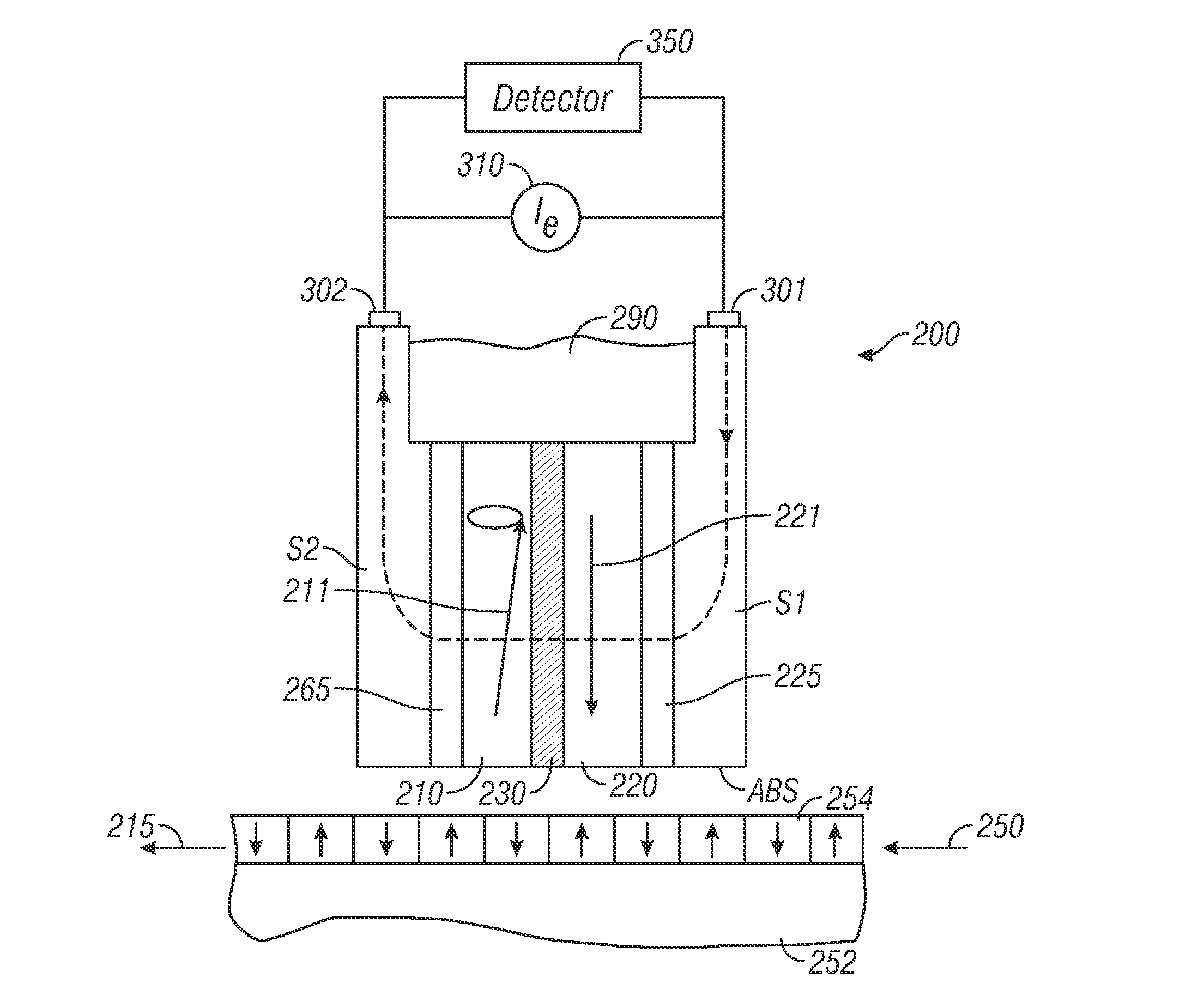
[0035]FIG. 5 is a schematic of a magnetic field sensing system using a STO sensor 200 according to the invention. The system is illustrated as a magnetic recording disk drive with STO sensor 200 with its ABS facing the disk 250. The sensor 200 includes a stack of individual layers of a CPP-GMR or CPP-TMR sensor as previously-described with respect to CPP sensor 100. The disk 250 has a substrate 252 and a recording layer 254 that serves as the magnetic recording medium with magnetized regions depicted by the arrows directed toward or away from the ABS. As the disk rotates, the magnetized regions move in the direction of arrow 215 past the sensor 200. The recording layer 254 is depicted as a perpendicular magnetic recording medium with the regions magnetized perpendicularly to the plane of recording layer 254, but alternatively it may be a longitudinal magnetic recording medium with the regions being magnetized in the plane of recording layer 254. The STO sensor 200 has a first shield...

second embodiment

[0039]FIG. 6 is a schematic of a magnetic field sensing system using a STO sensor 200 according to the invention. The embodiment of FIG. 6 is like that of FIG. 5 except that the free layer 210 is not doped, but is magnetically damped by a damping layer 212. Damping layer 212 is in contact with the side of free layer 210 opposite the side of free layer 210 that is adjacent to spacer layer 230. Damping layer 212 in FIG. 6 may be formed of an antiferromagnetic material, like a Mn alloy such as PtMn, NiMn, FeMn, IrMn, IrMnCr, PdMn, PtPdMn and RhMn alloys. For example, if free layer 210 is a CoFe ferromagnetic material with an intrinsic magnetic damping parameter of about 0.015, the addition of a 6 to 8 nm thick antiferromagnetic damping layer 212 formed of IrMn will increase the magnetic damping parameter to ˜0.1 [See N. Smith et al., Phys. Rev. B 81, 184431 (2010)]. As a modification to the antiferromagnetic damping layer 212, a bilayer damping layer may be formed of the antiferromagne...


PUM


Abstract

A spin-torque oscillator (STO) has increased magnetic damping of the oscillating free ferromagnetic layer. The Gilbert magnetic damping parameter (a) is at least 0.05, and preferably greater than 0.05. The free layer may be a any type of conventional ferromagnetic material, but contains one or more damping elements as a dopant. The damping element is selected from the group consisting of Pt, Pd and the 15 lanthanide elements. The free layer damping may also be increased by a damping layer adjacent the free layer. One type of damping layer may be an antiferromagnetic material, like a Mn alloy. As a modification to the antiferromagnetic damping layer, a bilayer damping layer may be formed of the antiferromagnetic layer and a nonmagnetic metal electrically conductive separation layer between the free layer and the antiferromagnetic layer. Another type of damping layer may be one formed of one or more of the elements selected from Pt, Pd and the lanthanides.

Description

BACKGROUND OF THE INVENTION[0001]1. Field of the Invention[0002]The invention relates generally to a spin-torque oscillator (STO), and more particularly to a magnetic field sensor and sensing system that uses a STO sensor.[0003]2. Background of the Invention[0004]One type of conventional magnetoresistive (MR) sensor used as the read head in magnetic recording disk drives is a “spin-valve” sensor based on the giant magnetoresistance (GMR) effect. A GMR spin-valve sensor has a stack of layers that includes two ferromagnetic layers separated by a nonmagnetic electrically conductive spacer layer, which is typically copper (Cu). One ferromagnetic layer adjacent the spacer layer has its magnetization direction fixed, such as by being pinned by exchange coupling with an adjacent antiferromagnetic layer, and is referred to as the reference layer. The other ferromagnetic layer adjacent the spacer layer has its magnetization direction free to rotate in the presence of an external magnetic fie...

Claims


Application Information

Patent Timeline
IPC IPC(8): H01S1/02
CPCG01R33/093G01R33/1284H03B28/00G11B2005/0005G11B5/3932G11B5/3903
Inventor BRAGANCA, PATRICK MESQUITAGURNEY, BRUCE ALVIN
Owner WESTERN DIGITAL TECH INC
Why Eureka
Try Eureka