Liquid droplet ejecting method, liquid droplet ejection apparatus, inkjet recording apparatus, production method of fine particles, fine particle production apparatus, and toner

a technology of liquid droplets and ejection apparatus, which is applied in the field of liquid droplet ejection method, liquid droplet ejection apparatus, and inkjet recording apparatus, can solve the problems of difficult to obtain a desired resonance frequency, difficult to set the resonance frequency high, and limit accuracy, so as to achieve high productivity, fine particle liquid droplets, and high density printing

Active Publication Date: 2013-01-10
RICOH KK
View PDF2 Cites 26 Cited by
  • Summary
  • Abstract
  • Description
  • Claims
  • Application Information

AI Technical Summary

Benefits of technology

[0048]The present invention can solve the above-mentioned conventional problems and achieve the object-described above. That is, the present invention can provide a liquid droplet ejecting method and a liquid droplet ejection apparatus each of which enables setting a desired resonance frequency, irrespective of fluid compliance of a liquid chamber and rigidity compliance of components such as an ejection hole plate, and producing extremely fine particle liquid droplets, and also provide an inkjet recording apparatus capable of achieving high-density printing.
[0049]Also, the present invention can solve the above-mentioned conventional problems and achieve the object described above. That is, the present invention can provide a production method of fine particles and a fine particle production apparatus each of which enables achieving continuous ejection of liquid owing to its ability of continuous driving, thereby which assures extremely high productivity and enables uniformly and stably producing extremely fine liquid droplets, and to provide a toner.

Problems solved by technology

Such inkjet recording apparatuses are widely prevalent because of their cheap costs and compactness.
Unfavorably, the processing technique for pressure generation chamber has a limitation on accuracy, and it is difficult to obtain a desired resonance frequency.
In addition, it is difficult to set the resonance frequency high, and thus the liquid droplet ejecting method has a problem that the liquid droplet diameter inversely proportional to the resonance frequency cannot be made small.
Further, the liquid droplet ejecting method disclosed in PTL 2 has a limit to eject microscopic liquid droplets using a high frequency, because the ejection holes are disposed in the direction of propagation of the standing wave.
Further, this toner production method has a problem that the liquid is pressurized in one direction, and toner components are clogged inside the nozzle depending on the composition of the toner.
In view of the time spared for the third state and the overall production process time, a time loss occurs, and the liquid ejection method has a problem that the toner production efficiency corresponding to the time loss is reduced.
Further, in the method disclosed in PTL4, generally, liquid droplets large in size are inconveniently formed, and thus, in order to obtain a dry-process toner particle, the ejection part must be made to have a small diameter or the materials must be diluted.
However, when the ejection part is reduced in size, inevitably, the probability of causing clogging of a solid dispersion of a pigment which is essentially added as a toner constituent element and a releasing agent etc. added as required dramatically increases, causing a problem with production stability.
In addition, when the toner material is diluted, the energy required for drying and solidifying the resulting diluent increases, which also greatly decreases the production efficiency.
Furthermore, a decrease of the production efficiency prolongs the time for storing the material liquid in the material reservoir part, and a retention of the material liquid occurs, which may consequently cause sticking of the toner material fractions in a long-term production period.

Method used


Image

  • Liquid droplet ejecting method, liquid droplet ejection apparatus, inkjet recording apparatus, production method of fine particles, fine particle production apparatus, and toner
  • Liquid droplet ejecting method, liquid droplet ejection apparatus, inkjet recording apparatus, production method of fine particles, fine particle production apparatus, and toner
  • Liquid droplet ejecting method, liquid droplet ejection apparatus, inkjet recording apparatus, production method of fine particles, fine particle production apparatus, and toner

Examples


example 1

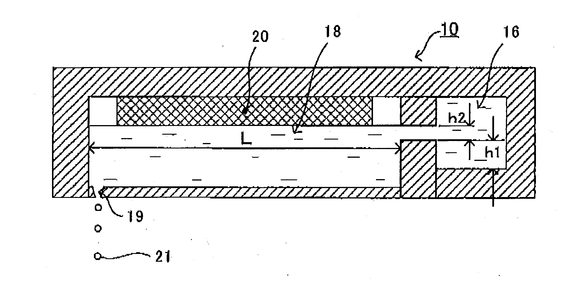
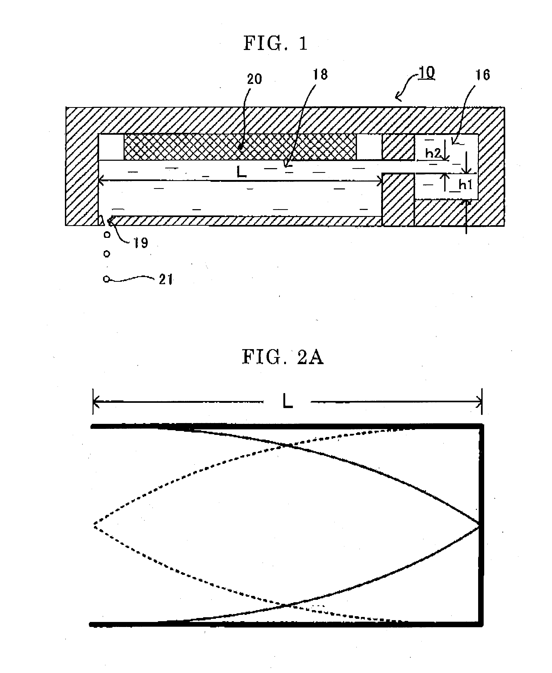
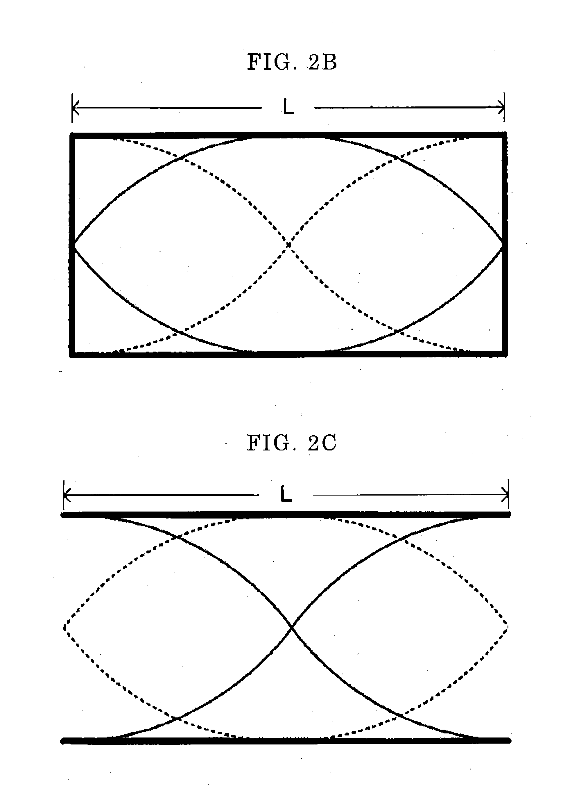
[0243]In Example 1, using a liquid droplet ejection head illustrated in FIG. 1, a waveform illustrated in FIG. 4 was applied to a piezoelectric element of the vibration generating unit to form liquid droplets. Note that a waveform of a main pulse part formed in a sine waveform corresponding to 300 kHz was formed once. The ejection hole was made by nickel electroforming with a pore diameter of 8 μm. A liquid column resonance-generating liquid chamber and a liquid supply path were formed by laminating a stainless steel path plate, to which a nickel thin film was laminated as an elastic plate. The piezoelectric element was disposed the upper part of the liquid column resonance-generating liquid chamber. These members are fixed with a stainless steel-made frame, as illustrated in FIG. 1. A mixture prepared in which a cyan pigment (0.5 parts by mass) was added to ethyl acetate (100 parts) and then a polyester resin for adjusting the viscosity was added thereto, and the mixture was added ...

example 2

[0244]In Example 2, the procedure of Example 1 was repeated except that the number of driving times of the waveform of the main pulse part was changed to two times. Thereafter, the same measurement for quantity of liquid droplet was performed. As a result, the quantity of one droplet measured with a pulse voltage of 8 V was found to be 1.2 pl.

example 3

[0245]In Example 8, the procedure of Example 1 was repeated except that the number of driving times of the waveform of the main pulse part was changed to three times. Thereafter, the same measurement for quantity of liquid, droplet was performed. As a result, in one driving, two liquid droplets were formed, and the quantity of one droplet measured with a pulse voltage of 8 V was found to be 1.8 pl. The quantity of liquid droplets can be modulated by changing the number of pulses of the main pulse part in this way.


PUM


Abstract

A liquid droplet ejecting method for ejecting a liquid from at least one ejection hole to form the liquid into liquid droplets, the method including: applying a vibration to the liquid in a liquid column resonance-generating liquid chamber, in which the ejection hole is formed, to form a standing wave through liquid column resonance, and ejecting the liquid from the ejection hole, which is formed in a region corresponding to an antinode of the standing wave, to form the liquid into liquid droplets.

Description

TECHNICAL FIELD[0001]The present invention relates to a liquid droplet ejecting method, a liquid droplet ejection apparatus, and an inkjet recording apparatus. The present invention also relates to a method for producing fine particles having uniform particle diameters by a spray granulation method, and a fine particle production apparatus. Further, the present invention relates to a toner produced by the production method of fine particles or the fine particle production apparatus.BACKGROUND ART[0002]Firstly, background art relating to an inkjet recording apparatus using a liquid droplet ejecting method, and a liquid droplet ejection apparatus will be described below.[0003]Inkjet recording apparatuses in current use are allowed to undergo displacement of a piezoelectric element etc. provided in a liquid chamber in an ink head to eject an ink in the liquid chamber from ink nozzles, in the form of ink droplets, and to adhere onto recording paper, thereby enabling printing on the reco...

Claims


Application Information

Patent Timeline
Patent Type & Authority Applications(United States)
IPC IPC(8): B41J2/045B05B17/04
CPCB41J2/14233B41J2202/02B41J2002/14475B41J2002/1425B01J2/02B41J2/14008B41J2/045B41J2/055
Inventor NORIKANE, YOSHIHIRONAKAMURA, HARUOOHGAKI, MASARUSEKIGUCHI, YUKO
Owner RICOH KK
Why Eureka
Try Eureka