Electrowetting display device

a display device and electro-rotor technology, applied in the field of electro-rotor-rotor-rotor display devices, can solve the problems of affecting the longevityaffecting affecting the ability of the display device to fully recover the quality of pristine hydrophobic surfaces, etc., to achieve the effect of improving the gray-scale capability of the display device, reducing the hydrophobicity of the area, and improving the switching behaviour of the pictur

Inactive Publication Date: 2013-01-10
LIQUAVISTA BV
View PDF9 Cites 21 Cited by
  • Summary
  • Abstract
  • Description
  • Claims
  • Application Information

AI Technical Summary

Benefits of technology

[0007]The method according to the invention allows a local lowering of the hydrophobicity of a predetermined area of the insulating layer by application of an electric field. The method does not require reducing and thereafter increasing the hydrophobicity of the surface, which affects the longevity of the display device. Since a display made by the method according to the invention is not subject to the process steps of decreasing and increasing the hydrophobicity, it has a better longevity. Moreover, annealing, used for increasing the hydrophobicity, does not fully recover the quality of a pristine hydrophobic surface. The method according to the invention does not require use of a photo-lithographic process for local lowering of the hydrophobicity as in the prior art. Hence, the number of process steps is reduced and there is less risk of delamination. The area of reduced hydrophobicity may be used for various purposes in the manufacture of the display device and / or in use of the display device. An area is said to have a reduced hydrophobicity if the area exerts a less repellent force on an electroconductive or polar fluid than an area having a non-reduced hydrophobicity; the force may become attractive when the hydrophobicity has been reduced sufficiently. The degree of hydrophobicity reduction of the area may be controlled by the strength of the electric field.
[0026]The pattern may form a barrier for the first fluid in a picture element. The barrier can be used in a bistable display device. A voltage pulse on an electrode can move the first fluid across the barrier; the barrier will keep the first fluid in position if the voltages are reduced to zero. Image content will be non-volatile. Hence, the power consumption of a display device using a barrier can be relatively low.

Problems solved by technology

The method does not require reducing and thereafter increasing the hydrophobicity of the surface, which affects the longevity of the display device.
Moreover, annealing, used for increasing the hydrophobicity, does not fully recover the quality of a pristine hydrophobic surface.
After the electric field has been switched off, part of the applied charge may leak away; however, another part stays permanently.

Method used


Image

  • Electrowetting display device
  • Electrowetting display device
  • Electrowetting display device

Examples


Embodiment Construction

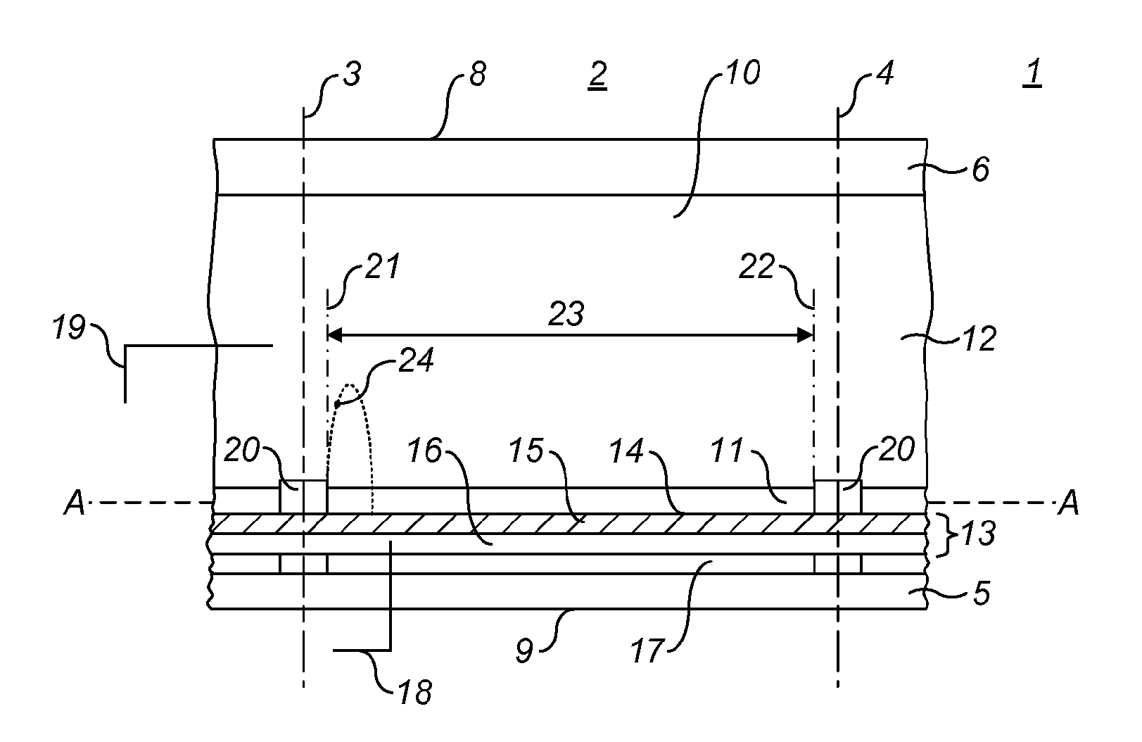
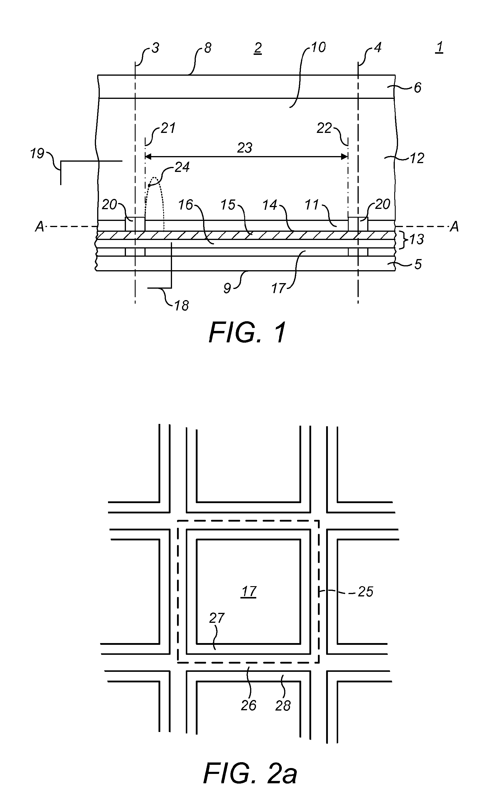
[0037]FIG. 1 shows a diagrammatic cross-section of part of an electrowetting display device 1. The display device includes a plurality of picture elements 2, one of which is shown in the Figure. The lateral extent of the picture element is indicated in the Figure by two dashed lines 3, 4. The picture elements comprise a first support plate 5 and a second support plate 6. The support plates may be separate parts of each picture element, but the support plates are preferably shared in common by the plurality of picture elements. The support plates may include a glass or polymer substrate and may be rigid or flexible.

[0038]The display device has a viewing side 8 on which an image or display formed by the display device can be viewed and a rear side 9. In the figure the first support plate 5 faces the rear side 9; the second support plate 6 faces the viewing side; alternatively, the first support plate may face the viewing side. The display device may be of the reflective, transmissive ...


PUM

PropertyMeasurementUnit
thicknessaaaaaaaaaa
thicknessaaaaaaaaaa
thicknessaaaaaaaaaa

Abstract

The present invention relates to a method for making an electrowetting display device comprising a plurality of picture elements and a first support plate and a second support plate. Each picture element comprises a space between the first support plate and the second support plate. The method comprises the steps of: providing the first support plate with an electrode structure; arranging an insulating layer on the electrode structure, the insulating layer having a thickness and a hydropobic surface facing the space; temporarily applying an electric field across the thickness of the insulating layer to reduce permanently the hydrophobicity of a predetermined area of the surface. The invention further relates to an electrowetting display device and a use of an area of reduced hydrophobicity in an electrowetting device.

Description

FIELD OF THE INVENTION[0001]The present invention relates to an electrowetting display device and a method for making the same.BACKGROUND OF THE INVENTION[0002]An electrowetting display device, such as described in the international patent application WO 2003 / 071346, includes two support plates. A pattern of walls is arranged on one of the support plates, the pattern defining the picture elements of the display device. The area between the walls of a picture element, also known as a pixel, is called the display area, over which a display effect occurs. The walls of the picture elements are made of a hydrophilic material. The area of the support plate in the display area must to a large extent be hydrophobic for a proper operation of the picture element. During manufacture the area of the support plate where the picture elements are located is covered by a hydrophobic layer. The walls are made on this layer by depositing a layer of wall material onto the hydrophobic layer and pattern...

Claims


Application Information

Patent Timeline
Patent Type & Authority Applications(United States)
IPC IPC(8): G02B26/00H01R43/00
CPCY10T29/49117G02B26/005G02B26/02
Inventor MASSARD, ROMARICHAYES, ROBERTFEENSTRA, BOKKE JOHANNES
Owner LIQUAVISTA BV
Why Eureka
Try Eureka