
LED lamp for homogeneously illuminating hollow bodies

Active Publication Date: 2013-01-10
HERAEUS NOBLELIGHT GMBH
View PDF7 Cites 40 Cited by
  • Summary
  • Abstract
  • Description
  • Claims
  • Application Information

AI Technical Summary

Benefits of technology

The invention is a lighting device that uses COB technology, which allows for the use of a wide range of construction and connection materials. This technology offers flexibility and cost-effectiveness when creating powerful LED lamps and also provides good bendability of small pipes even in 90-degree bends. The device uses multiple LED modules that can be coupled flexibly and pulled through a pipe to output the necessary dose of radiation for curing a light-reactive coating while also allowing for a sufficient pulling speed. The invention has been particularly useful in the field of duct and pipe relining, where it provides high-intensity lighting with uniform radiation distribution and good bendability.

Problems solved by technology

In duct relining, this can result in thermal damage in the liner material to be cured.
The known lamps are suitable, above all, for larger pipe diameters, but due to their overall size are less suitable for smaller pipe diameters, for example in building connections, having typical pipe diameters corresponding to a nominal diameter of 160 mm or smaller.
There are no gas-discharge lamp systems of this size available, that can be pulled through curves having angles of 45° or 90°.
For small overall sizes, the traditional UV lamp technology is limited by the achievable minimum size of the lamps.
Another limitation in this respect is also due to the requirement for a mechanically robust holder and protective device for the lamps, which usually consist of a glass enveloping body filled with a substance, in which the gas discharge takes place between two opposing electrodes or by an electrode-less excitation with microwaves.
These inhomogeneities in the emissions are disadvantageous, if a uniform irradiation is required, for example in UV curing.
In particular, the use of several traditional glass bulb lamps for achieving high irradiation intensities makes it more difficult to achieve a homogeneous illumination due to the significant geometric expansion of these lamps, when these are arranged one next to the other in the peripheral direction, for example of a pipe.
This results from the fact that a good overflow of the emitted radiation fields takes place only at a geometric spacing corresponding to the spacing of the emission centers, so that drops in the radiation intensity due to the lack of emissions between the emission centers of the lamps lead to strong inhomogeneities in the peripheral direction.
In this case, possibly expensive optics must be used for the homogenization of the illumination.

Method used


Image

  • LED lamp for homogeneously illuminating hollow bodies
  • LED lamp for homogeneously illuminating hollow bodies
  • LED lamp for homogeneously illuminating hollow bodies

Examples


Embodiment Construction

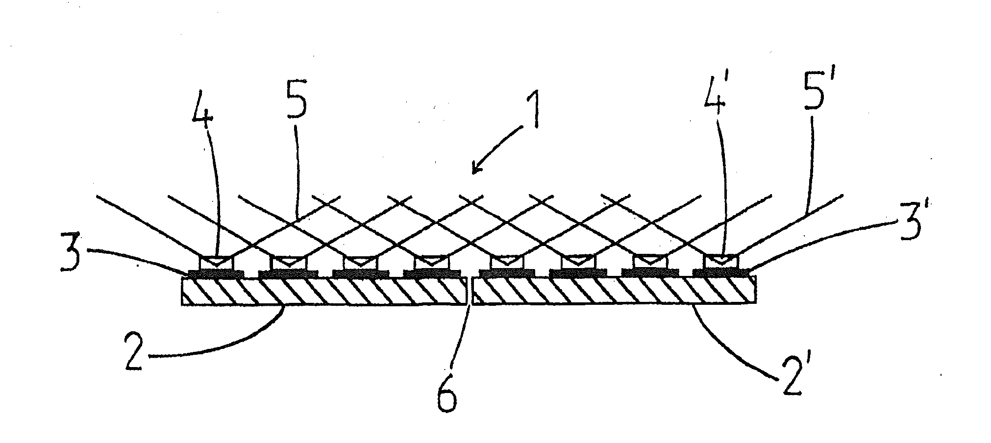
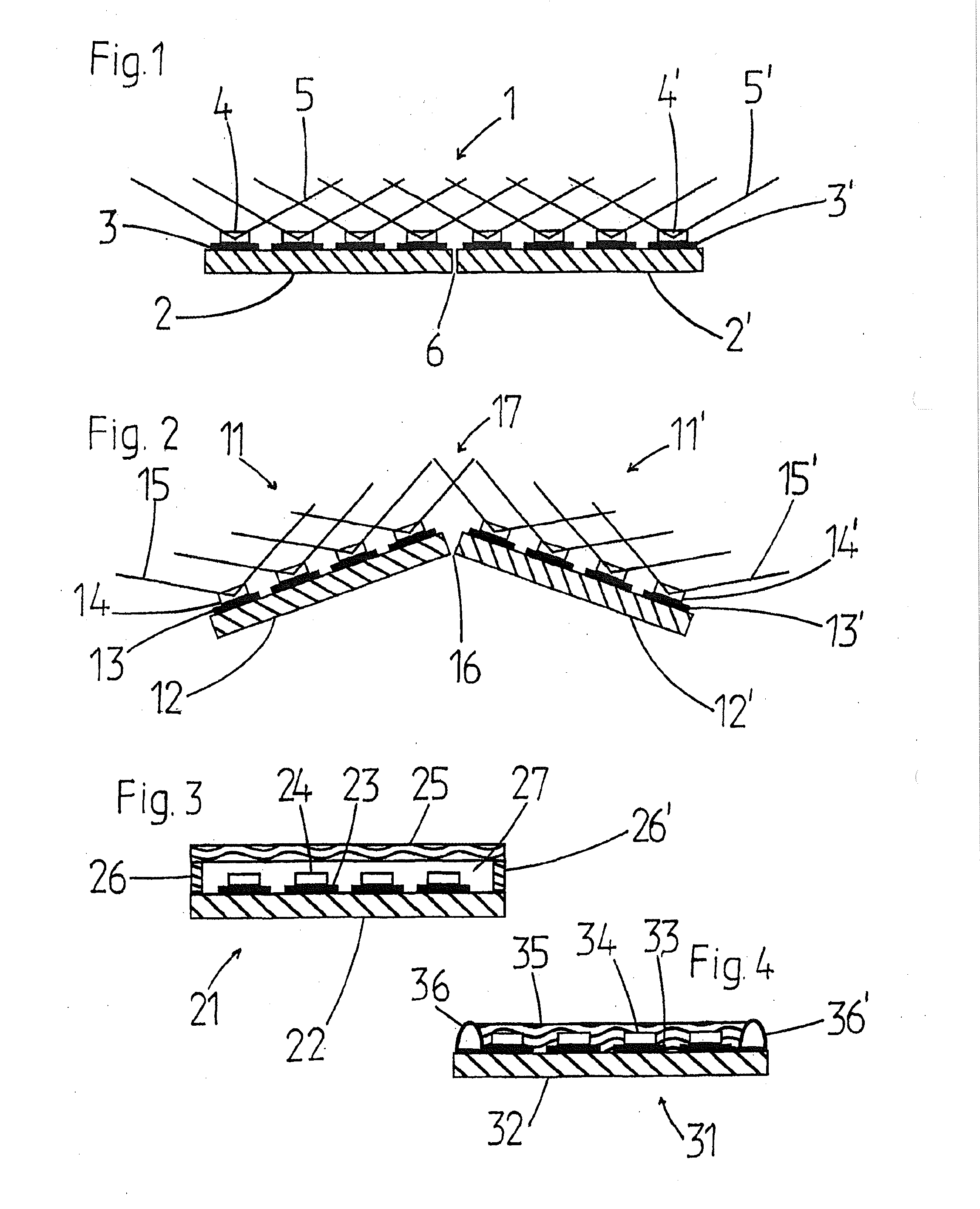
[0064]In FIG. 1 a chip-on-board LED module 1 is shown schematically in cross section, in which strip conductors 3, 3′ and LED Chips 4, 4′ are arranged at a regular spacing on two substrates 2, 2′ arranged in parallel. One substrate 2, 2′ can be, for example, a metal core conductor plate, a ceramic substrate, or an FR4 substrate, which can be constructed using a rigid, semi-flexible, or flexible substrate technology. For reasons of clarity, not all of the repeating elements in FIG. 1 are provided with reference symbols, but these symbols refer to all equivalent elements.

[0065]The light cones 5, 5′ of the LED chips 4, 4′ are shown with lines. The LEDs are approximately Lambert radiators, which emit approx. 75% of the total emitted light power within an opening angle of 120°. A good overlap of the emission cones 5, 5′ at the boundaries of adjacent LED chips 4, 4′ is already given at spacings on the order of magnitude of the chip spacings, also called “pitch,” so that no significant int...


PUM


Abstract

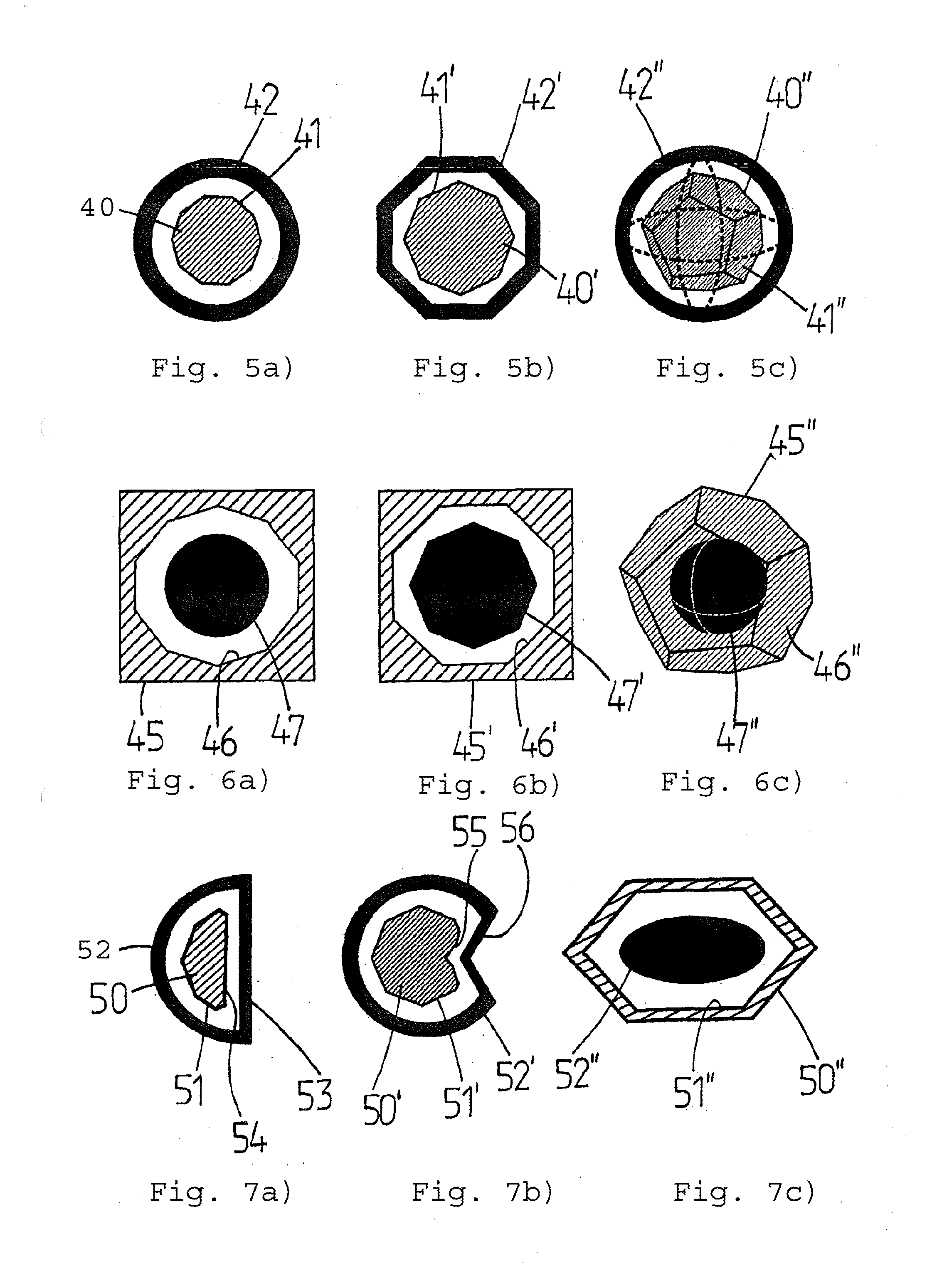
A lighting device (40-40″, 45-45″, 50-50″, 60, 80, 93-93″) is provided for the uniform illumination of curved, uneven, or polyhedral surfaces. The lighting device has a plurality of flat chip-on-board LED modules (1, 11, 11′, 21, 31, 41-41″, 46-46″, 51-51″, 61-61″, 71-71′″, 811-818), which are arranged adjacent to each other at least in pairs. Each chip-on-board LED module (1, 11, 11′, 21, 31, 41-41″, 46-46″, 51-51″, 61-61″, 71-811-818) has a plurality of light-emitting LEDs (4, 4′, 14, 14′, 24, 34, 64, 72). The lighting device (40-40″, 45-45″, 50-50″, 60, 80, 93-93″) is characterized by at least one pair of the adjacent chip-on-board LED modules (1, 11, 11′, 21, 31, 41-41″, 46-46″, 51-51″, 61-61″, 71-71′″, 811-818) being arranged at an angle greater than 0° with respect to the surface normals of the modules.

Description

CROSS-REFERENCE TO RELATED APPLICATIONS[0001]This application is a Section 371 of International Application No. PCT / EP2011 / 001510, filed Mar. 25, 2011, which was published in the German language on Oct. 13, 2011, under International Publication No. WO 2011 / 124331 A1 and the disclosure of which is incorporated herein by reference.BACKGROUND OF THE INVENTION[0002]The invention relates to a lighting device for the uniform illumination of curved, uneven, or polyhedral surfaces, comprising a plurality of flat chip-on-board LED modules, which are arranged adjacent to each other at least in pairs, wherein each chip-on-board LED module has a plurality of light-emitting LEDs. The invention further relates to an lighting unit and a use.[0003]One field of application that requires a uniform illumination of curved, polyhedral, or uneven surfaces is the curing and light exposure needed for drying, hardening, or exposure of lacquers, adhesives, resins, and other light-reactive materials, with whi...

Claims


Application Information

Patent Timeline
IPC IPC(8): F21V21/00F21V7/00F21V5/04F21V11/00F21V29/00
CPCF21K9/00F21Y2111/005F21Y2101/02F21K9/20F21V19/001F21V23/003F21V23/04F21Y2115/10F21Y2107/30
Inventor PEIL, MICHAELOSWALD, FLORINMAIWEG, HARALD
Owner HERAEUS NOBLELIGHT GMBH
Learn More