Polarized white light emitting diode

a light-emitting diode and polarized technology, applied in the field of white light-emitting diodes, can solve the problems of easy exhaustion of the operation of the reflective polarized multi-sheets made from polymer, user discomfort, damage, etc., and achieve the effect of increasing the extinction ratio of the polymer, reducing the color temperature thereof, and reducing the color temperatur

Inactive Publication Date: 2013-01-17
NAT TAIWAN UNIV OF SCI & TECH
View PDF1 Cites 32 Cited by
  • Summary
  • Abstract
  • Description
  • Claims
  • Application Information

AI Technical Summary

Benefits of technology

[0012]Accordingly, the object of the invention is to provide a polarized white light emitting diode for increasing the extinction ratio thereof, decreasing the color temperature thereof, retarding the variation of the color thereof, and further improving the uniformity thereof. Otherwise, the polarized white light emitting diode can be useful for the back-lighting of the liquid crystal displays (LCDs) to increase the illumination and to decrease the usage of the polarizing sheet so as to solve the exhaustion of the polarizing sheet.

Problems solved by technology

The disadvantages of the white LED formed by multiple color phosphor powders and the ultraviolet light emitting diode chip are the insufficient illumination and causing damage due to the ultraviolet light.
However, the intensity of the blue light is larger than the intensity of the yellow light in the mixing process of said white LED, so the disadvantage of said white LED are high color temperature and glare caused, so the color rendering is unable to rise to 80 and the illumination and the color are not uniform to produce yellow circle phenomenon.
In illumination application, the non-polarized light causes glare so user feels uncomfortable as reading under the non-polarized light.
How to make the white light emitted from the white LED polarize, own high extinction ration and decrease glare is an urgent problem in the field.
However, the reflective polarized multi-sheets made from polymer is easy exhaustion in the operation due to the high operation temperature and the exposure under the ultraviolet light.
Thus, how to make the reflective polarized multi-sheets durable is another urgent problem in the field.
However, the nanometer structure of the reflective metallic wire-grid polarizer is easy-damaged, so how to protect the reflective metallic wire-grid polarizer is another urgent problem in the field.

Method used


Image

  • Polarized white light emitting diode
  • Polarized white light emitting diode
  • Polarized white light emitting diode

Examples


first embodiment

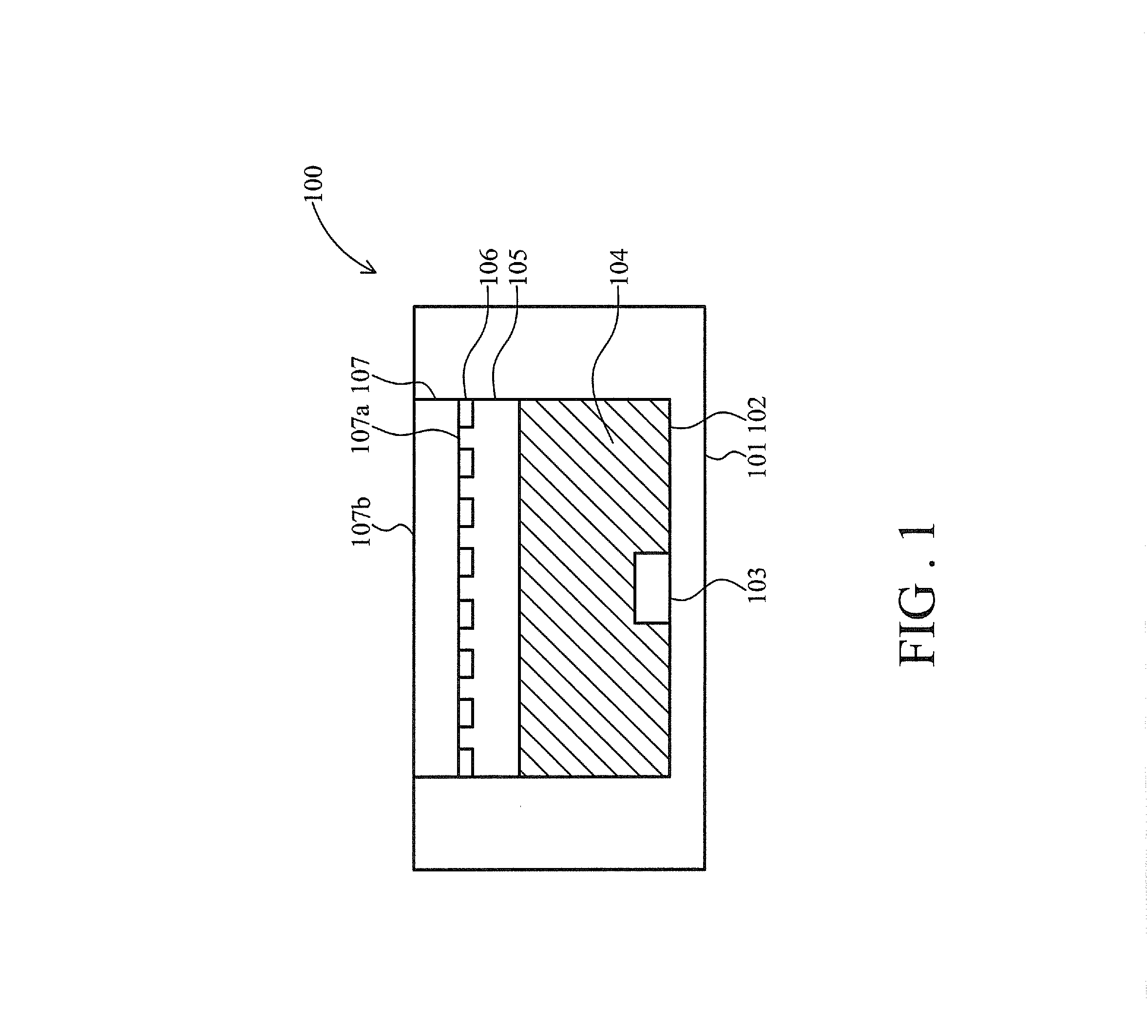
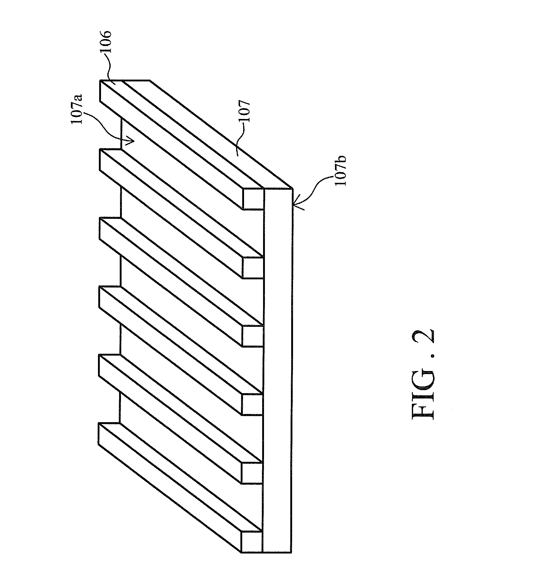
[0031]Refer to FIG. 1 for a schematic view of a polarized white light emitting diode of the invention. The polarized white light emitting diode 100 includes a reflection substrate 101, a light emitting diode chip 103, a phosphor layer 104, a metallic wire-grid polarizing layer 106 and a transparent substrate 107.

[0032]The reflection substrate 101 has a bottom and four walls, so a concave is formed by the bottom and the walls. The light emitting diode chip 103 is disposed above the bottom of the reflection substrate 101, and a circuit (without drawn) is formed on reflection substrate 101 so the light emitting diode chip 103 is electrically connected with circuit. The light emitting diode chip 103 is driven by external current to emit a first color light and further provide the first color light for exciting the phosphor layer 104. Wherein the first color light has a transverse electric wave (TE wave) and a transverse magnetic wave (TM wave). In this embodiment, the first color light ...

second embodiment

[0044]Refer to FIG. 3 for a schematic view of the polarized white light emitting diode of the invention. The different structure between the polarized white light emitting diodes 100 and 100a is the air gap. The air gap 105 of the polarized white light emitting diodes 100 is replaced to an air gap 105b and a material 105a such as transparent gel in the polarized white light emitting diodes 100a. The reflective index of the medium 105b is between 1 and 1.4, and is smaller than the reflective index of the phosphor layer 104.

third embodiment

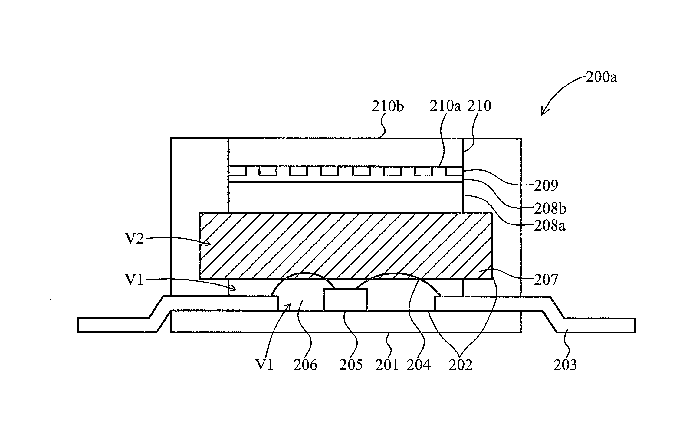
[0045]Refer to FIG. 4 for a schematic view of the polarized white light emitting diode of the invention. A polarized white light emitting diode 100b further includes a secondary optical unit 108 disposed on the second surface 107b of the transparent substrate 107. Wherein the secondary optical unit 108 is such as a flat sheet, a micro-lens, an optical film or an optical grating. In this embodiment, the secondary optical unit 108 is a micro-lens array, so the directivity of the polarized white light emitted from the polarized white light emitting diode 100b is improved by the micro-lens array.


PUM


Abstract

A polarized white light emitting diode provides a polarized white light to decrease glare, and increase the extinction ratio. A LED chip is disposed in a cavity between a reflection substrate and a metallic wire-grid polarizing layer, and emits a first color light. The metallic wire-grid polarizing layer is disposed under and in contact with a transparent substrate. A phosphor layer covers over the LED chip, and is disposed in the cavity with an air gap between the phosphor layer and the metallic wire-grid polarizing layer. A second color light is generated by the first color light. The metallic wire-grid polarizing layer multiply reflects a portion of first color light in plural directions in the cavity to produce secondary excitations. The polarized white light transmits through the metallic wire-grid polarizing layer by mixing a portion of first color light with the second color light excited by the first color light.

Description

BACKGROUND OF THE INVENTION[0001]1. Field of the Invention[0002]The invention relates to a white light emitting diode, and especially relates to a polarized white light emitting diode.[0003]2. Description of the Prior Art[0004]A white light emitting diode (LED) is formed by plural color light emitting diode chips. Another white light emitting diode (LED) is mostly formed by multiple color phosphor powders and one of the blue light emitting diode chip and the ultraviolet light emitting diode chip.[0005]Though the first white LED formed by plural color light emitting diode chips has the capability for the adjustable color light, the different materials of plural color light emitting diode chips could make the color temperature rise up following the varied color and the hard mixing of the color light and etc. The disadvantages of the white LED formed by multiple color phosphor powders and the ultraviolet light emitting diode chip are the insufficient illumination and causing damage due...

Claims


Application Information

Patent Timeline
Patent Type & Authority Applications(United States)
IPC IPC(8): H01L33/50
CPCH01L33/486H01L33/507H01L33/58H01L2933/0091H01L2224/48247H01L2224/48091H01L2924/00014
Inventor SU, JUNG-CHIEH
Owner NAT TAIWAN UNIV OF SCI & TECH
Why Eureka
Try Eureka