Fluorescent layer and its preparation method and uses

Inactive Publication Date: 2013-01-17
BELL CERAMICS
View PDF1 Cites 5 Cited by
  • Summary
  • Abstract
  • Description
  • Claims
  • Application Information

AI Technical Summary

Problems solved by technology

However, such a device is limited in application to light emitting devices requiring high luminance due to a large volume, poor luminous efficiency and uneven color mixing.
Nonetheless, the above light emitting device, when used for a time period, often has the problem of aging (etiolation) because the epoxy resin therein is over-crosslinked due to the absorption of ultraviolet light or heat generated by the diode.
This aging problem lowers the luminous efficiency of the light emitting devices significantly.
In addition, the fluorescent material in the light emitting layer a

Method used


Image

  • Fluorescent layer and its preparation method and uses
  • Fluorescent layer and its preparation method and uses
  • Fluorescent layer and its preparation method and uses

Examples


example

[Preparation of a Fluorescent Layer]

[0044]BaCO3, Al2O3 and SiO2 were weighed in a molar ratio of 2.5:1:10 and were wet milled using aluminum oxide balls for 30 minutes, and then, the obtained milled slurry was dried to obtain a precursor mixture of a calcining material. Next, a thermal treatment on the precursor mixture was performed at about 850° C. for about 4 hours to obtain a calcining material 2.5(BaO)•Al2O3•10(SiO2).

[0045]Y2.93Al5O12:Ce0.07 and the obtained calcining material 2.5(BaO)•Al2O3•10(SiO2) were weighed in a weight ratio of 40:60, ground and mixed with each other. Then, the mixture was pressed to form a green thin layer with a thickness of about 1 mm via dry pressing.

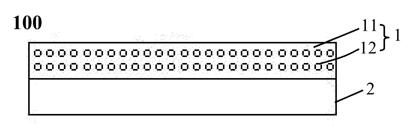
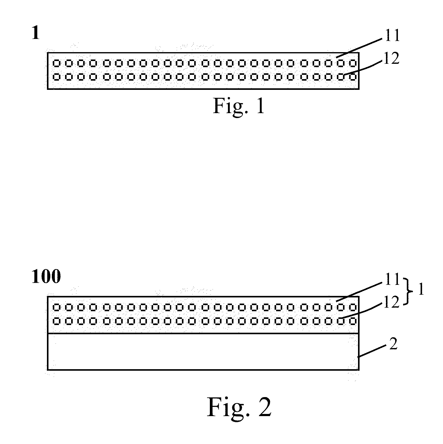
[0046]A thermal treatment was performed on the obtained green thin layer in an air atmosphere at about 1140° C. for about 2 hours to obtain a fluorescent layer F with a thickness of about 0.8 mm, as shown in FIG. 1.

[Preparation of a Sapphire Fluorescent Plate]

[0047]BaCO3, Al2O3 and SiO2 were weighed in a ...


PUM

PropertyMeasurementUnit
Temperatureaaaaaaaaaa

Abstract

A fluorescent layer, its preparation method and uses are provided. The fluorescent layer is provided from a fluorescent material and a calcining material. The fluorescent material is in an amount ranging from about 5 wt % to about 95 wt % based on the total weight of the fluorescent layer. The fluorescent layer of the present invention can be used in a light-emitting diode to change the color of emitting-light and improve the heat dissipation of the light-emitting diode. Furthermore, the fluorescent layer of the present invention is free of an organic resin, and thus, does not have the problem of aging (etiolation). The final product has a stable, lasting and durable luminescent quality.

Description

CLAIM FOR PRIORITY[0001]This application claims the benefit of Taiwan Patent Application No. 100124605, filed Jul. 12, 2011, and Taiwan Patent Application No. 101111384, filed Mar. 30, 2012, the subject matters of which are incorporated herein by reference.CROSS-REFERENCES TO RELATED APPLICATIONS[0002]Not applicable.BACKGROUND OF THE INVENTION[0003]1. Field of the Invention[0004]The present invention relates to a fluorescent layer and its preparation method and uses. In particular, the present invention relates to a fluorescent layer useful in light emitting diodes and its preparation method.[0005]2. Descriptions of the Related Art[0006]With the awareness of saving energy and protecting the environment, white light emitting diodes (LEDs) have become the most anticipated emerging product and have gradually replaced traditional lighting equipments because of advantages including a smaller size (in response to the trend of miniaturization), low power consumption (one eighth to one tent...

Claims


Application Information

Patent Timeline
IPC IPC(8): C09K11/80C09K11/59H01J1/63B32B9/00B29C71/02B32B37/14C09K11/08C09K11/64
CPCC04B35/195C04B2235/3229C09K11/025C04B2235/3225C04B35/44H01L33/502C04B2235/80C04B2235/3222C04B35/16C04B2235/764C04B2235/3215C09K11/7774C04B35/62645
Inventor CHIANG, TE-HSINLIU, RU-SHICHIANG, DER-SHINGCHIANG, CHANG-YANG
Owner BELL CERAMICS
Why Eureka
Try Eureka