Media Conveyance Device, Printing Device, and Media Conveyance Method

a technology of media conveyance and printing device, applied in the field of media conveyance devices, can solve the problems of increasing the time or distance needed to stop, media can become jammed in the structural members of the conveyance path, and re-acceleration while slowing, so as to prevent media jams, improve throughput, and short time

Active Publication Date: 2013-01-17
SEIKO EPSON CORP
View PDF0 Cites 1 Cited by
  • Summary
  • Abstract
  • Description
  • Claims
  • Application Information

AI Technical Summary

Benefits of technology

[0010]A conveyance device according to the invention conveys sheet media stored in a roll, executes a media reversing operation in a short time, improve throughput, conveys the media precisely during the reversing operation, and prevents media jams.

Problems solved by technology

However, if a control method that tracks a predetermined deceleration curve (a speed curve over time) is used in the conventional reversing operation described above as the method of slowing and stopping rotation of the roll media when stopping operation, unstable behavior, such as re-acceleration while slowing, can occur due to inertia changing with the roll diameter.
This can then result in an increase in the time or distance needed to stop.
Because this shift occurs easily particularly when the roll diameter is large and is amplified with propagation downstream, the media can become jammed in the structural members of the conveyance path when the shift is great.
Furthermore, while stopping reverse rotation of the paper roll without delay is described in JP-A-H06-144664, a specific method is not disclosed, and what to do about movement of the paper due to roll paper inertia is not addressed.
As a result, when the paper shifts from the correct position, time is required to correct the position.
There is also a problem with the precision of the stopping position because there is no awareness of the stopping position in the conveyance direction and the inertia of the paper roll when driving stops is not considered.

Method used


Image

  • Media Conveyance Device, Printing Device, and Media Conveyance Method
  • Media Conveyance Device, Printing Device, and Media Conveyance Method
  • Media Conveyance Device, Printing Device, and Media Conveyance Method

Examples


Embodiment Construction

[0033]A preferred embodiment of the present invention is described below with reference to the accompanying figures. It will be apparent to those skilled in the art in light of the following disclosure that the scope of the invention is not limited by the embodiment described below. Note also that identical or similar parts are described using the same reference numerals or symbols in the accompanying figures.

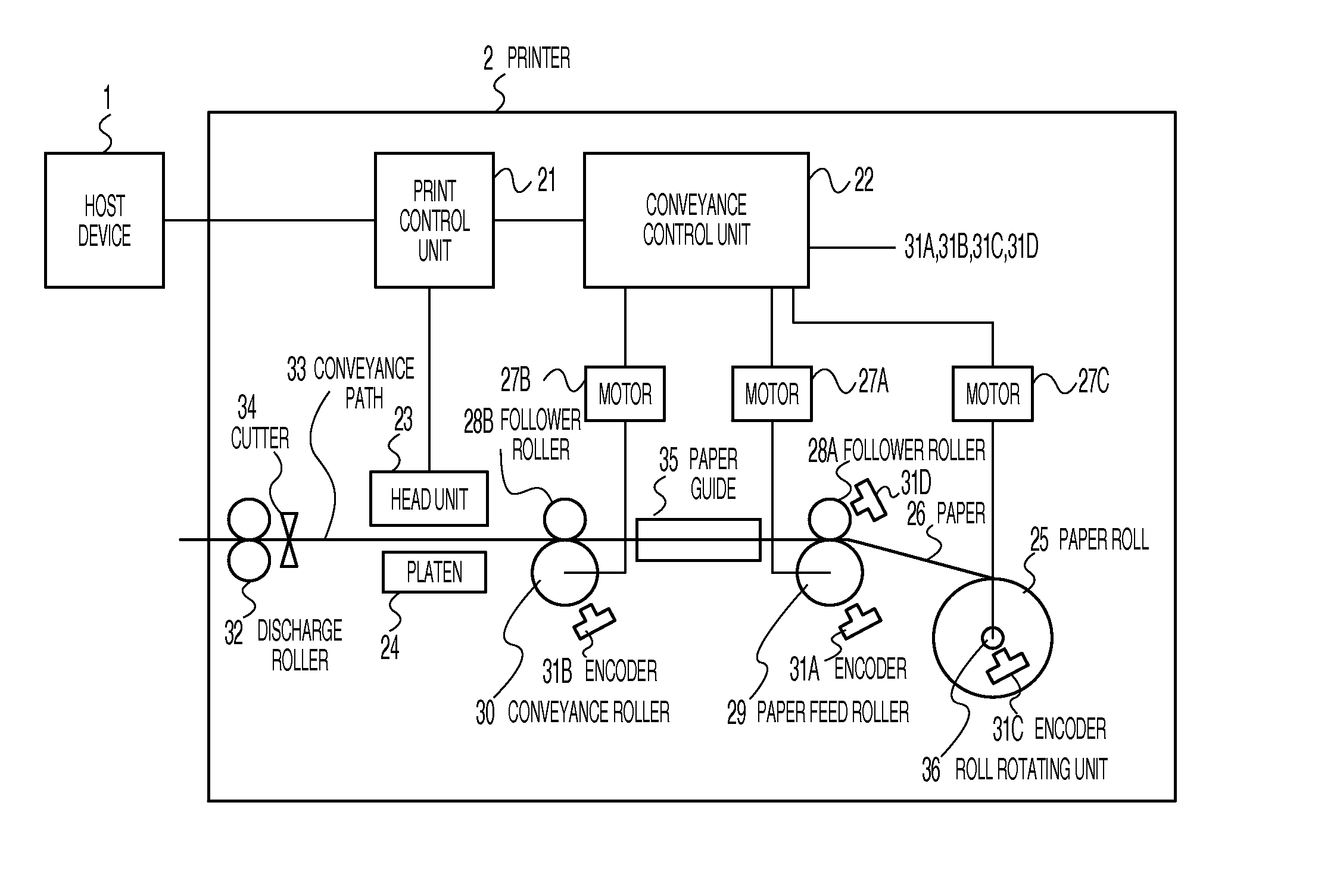
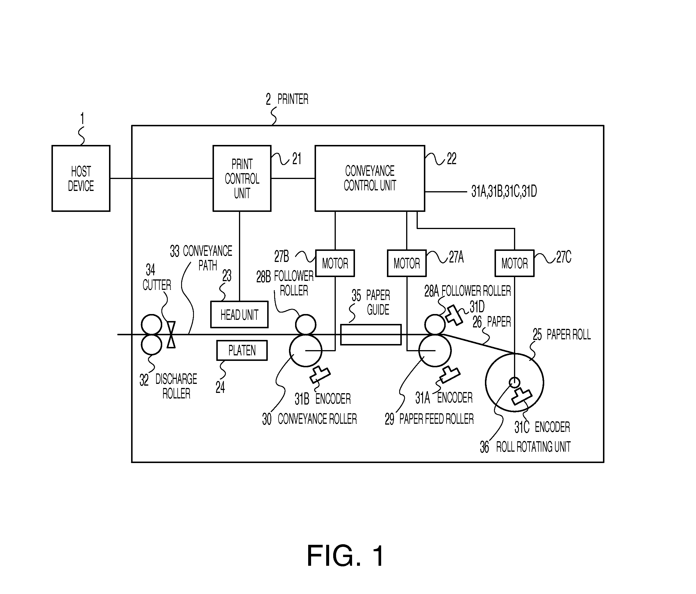
[0034]FIG. 1 is a block diagram of a preferred embodiment of a printer having a conveyance device according to a preferred embodiment of the invention. The printer 2 shown in FIG. 1 executes a printing process that conveys paper 26 stored in a roll to a printing position using a paper feed roller 29 (upstream roller) and conveyance roller 30 (downstream roller).

[0035]During reverse conveyance, or more specifically when the paper 26 (wound in paper roll 25 in this embodiment) is rewound to a specific position between jobs, for example, the conveyance of paper 26 is reversed by d...


PUM

PropertyMeasurementUnit
speedaaaaaaaaaa
timeaaaaaaaaaa
pressureaaaaaaaaaa

Abstract

A conveyance device has a roll rotating unit that rotates a roll of sheet medium forward and in reverse, and a conveyance path along which is an upstream roller and a downstream roller for conveying the medium and cooperate in a reverse and rewind operation. A control unit controls driving of the upstream roller, the downstream roller, and the roll rotating unit, such that, during the reverse and rewind operation, the control unit (i) drives the upstream roller and the roll rotating unit, (ii) stops driving the upstream roller while continuing to drive the roll rotating unit, first slack being created as a result of (i) or (ii), (iii) causes the medium to be nipped at the downstream roller, and (iv) drives the upstream roller while the medium is nipped at the downstream roller to create second slack.

Description

RELATED APPLICATION(S)[0001]This application claims priority under 35 U.S.C. §119 on Japanese application nos. 2011-152870 and 2011-153711, filed Jul. 11, 2011 and Jul. 12, 2011, respectively. The content of each such application is incorporated herein by reference.BACKGROUND[0002]1. Technical Field[0003]The present invention relates to conveyance devices that convey sheet media stored in a roll, and relates more particularly to media conveyance devices that can perform a reversing operation in a short time, convey media accurately in reverse, improve throughput, and prevent paper jams.[0004]2. Related Art[0005]Receipt printers and other devices that process sheet media (such as paper) stored in a roll have a device for conveying the media to a processing position. The conveyance device usually has an upstream roller that feeds the media from the roll to the conveyance path, and a downstream roller that supplies the fed media to the processing position, and the media is conveyed by ...

Claims


Application Information

Patent Timeline
Patent Type & Authority Applications(United States)
IPC IPC(8): B41J2/00B65H43/00
CPCB65H20/38B65H20/40B65H2301/51212B65H2513/114B65H2404/143B65H2404/742B65H2403/942B65H2513/11
Inventor NOGUCHI, AKIHIKOHAMAKAWA, HIROSHIISHIDA, TETSUGO
Owner SEIKO EPSON CORP
Why Eureka
Try Eureka