Optical fiber-type optical element, laser diode module, and fiber laser

Inactive Publication Date: 2013-01-17
THE FUJIKURA CABLE WORKS LTD
View PDF5 Cites 17 Cited by
  • Summary
  • Abstract
  • Description
  • Claims
  • Application Information

AI Technical Summary

Benefits of technology

[0034]An optical fiber-type optical element of the present invention, as described in the foregoing, includes: a core section provided so as to extend in a light-guiding direction in which incident light propagates; a photosensitive layer provided so as to extend in the light-guiding direction and peripherally enclose the core section, the photosensitive layer including a refractive index grating formed therein by irradiation with ultraviolet light having a predetermined wavelength; and a cladding section provided between the core section and the photosensitive layer, t

Problems solved by technology

Therefore, if the light coupled into the cladding section was absorbed by a coating section or a metal coating section formed in peri

Method used


Image

  • Optical fiber-type optical element, laser diode module, and fiber laser
  • Optical fiber-type optical element, laser diode module, and fiber laser
  • Optical fiber-type optical element, laser diode module, and fiber laser

Examples


first embodiment

1. First Embodiment

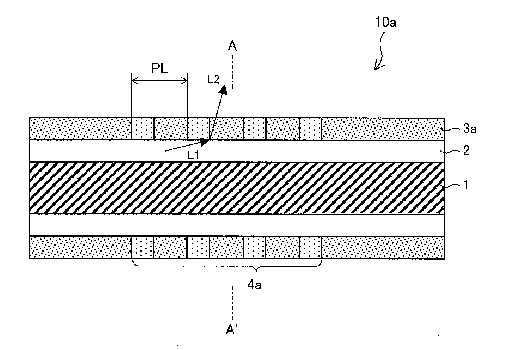
[0045]First, an optical fiber-type optical element 10a, which is an embodiment of the present invention, will be described in reference to FIG. 1.

[0046]FIG. 1, representing an arrangement of the optical fiber-type optical element 10a, is a cross-sectional view taken on a plane containing a central axis of a core section 1 (top), a cross-sectional view of the optical fiber-type optical element 10a taken along line A-A′ (middle), and a graph representing a refractive index distribution in the A-A′ cross-section (bottom).

[0047]As illustrated in FIG. 1, the optical fiber-type optical element 10a has a circular A-A′ cross-section and includes a core section 1, a first cladding section (cladding section) 2, and a photosensitive layer 3a. The core section 1 extends in a light-guiding direction in which incident light propagates. The first cladding section (cladding section) 2 is of a substantially circular ring-like shape in its A-A′ cross-section and extends in the ligh...

second embodiment

2. Second Embodiment

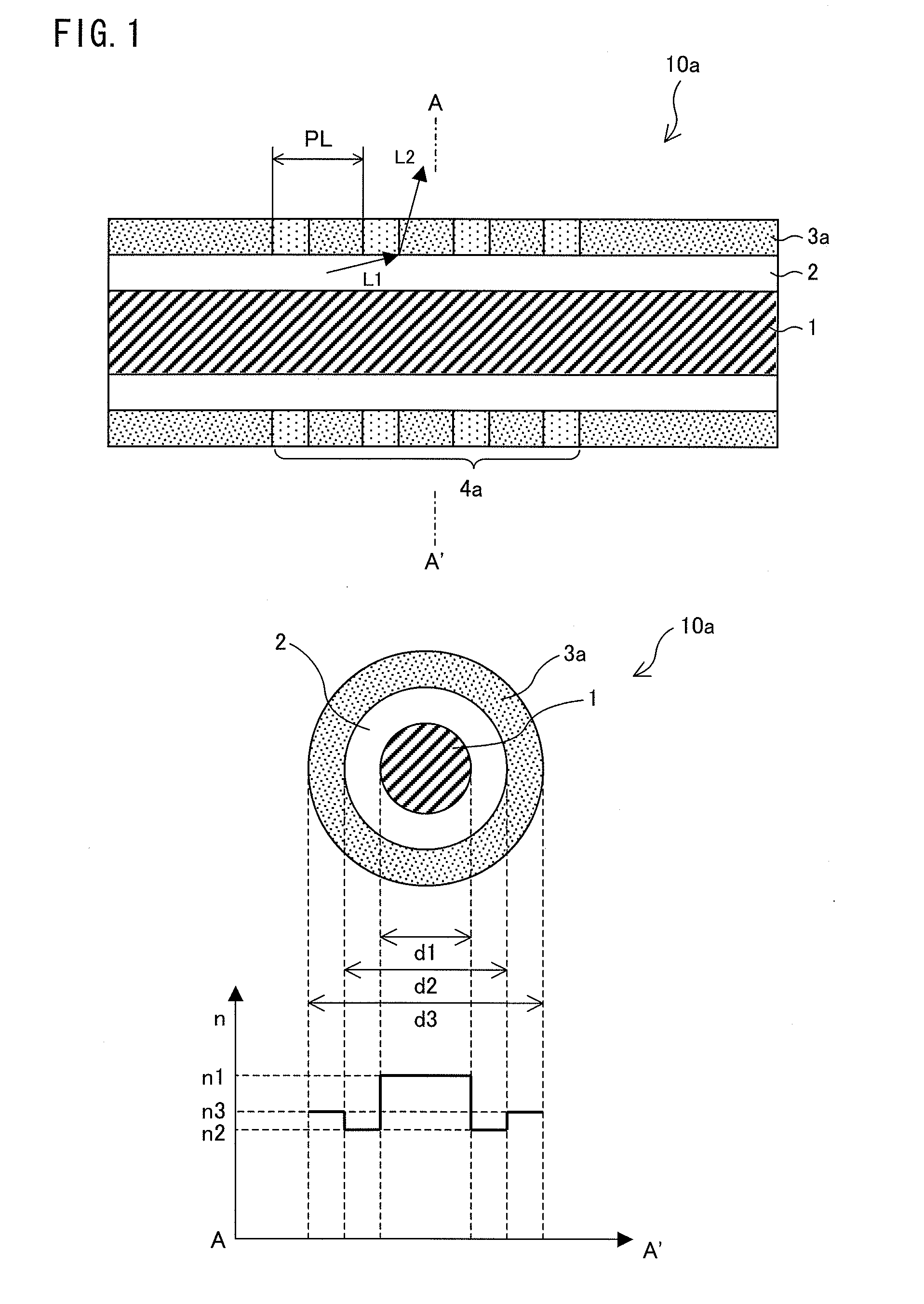
[0079]Next, an optical fiber-type optical element 10b, which is another embodiment of the present invention, will be described in reference to FIG. 2.

[0080]FIG. 2, representing an arrangement of the optical fiber-type optical element 10b, is a cross-sectional view taken on a plane containing a central axis of a core section 1 (top), a cross-sectional view of the optical fiber-type optical element 10b taken along line B-B′ (middle), and a graph representing a refractive index distribution in the B-B′ cross-section (bottom).

[0081]The optical fiber-type optical element 10b is a so-called double cladding fiber. As illustrated in FIG. 2, the optical fiber-type optical element 10b has a circular B-B′ cross-section and includes a core section 1, a first cladding section 2, a photosensitive layer 3b, and a second cladding section (cladding section) 5. The core section 1 extends in a light-guiding direction in which incident light propagates. The first cladding section 2 ...

third embodiment

3. Third Embodiment

[0097]Next, an optical fiber-type optical element 10c, which is an embodiment of the present invention, will be described in reference to FIG. 3.

[0098]FIG. 3, representing an arrangement of the optical fiber-type optical element 10c, is a cross-sectional view taken on a plane containing a central axis of a core section 1 (top), a cross-sectional view of the optical fiber-type optical element 10c taken along line A-A′ (middle), and a graph representing a refractive index distribution in the A-A′ cross-section (bottom).

[0099]As illustrated in FIG. 3, the optical fiber-type optical element 10c has a circular A-A′ cross-section and includes a core section 1, a first cladding section (cladding section) 2, and a photosensitive layer 3c. The core section 1 extends in a light-guiding direction in which incident light propagates. The first cladding section (cladding section) 2 is of a substantially circular ring-like shape in its A-A′ cross-section and extends in the light...


PUM


Abstract

There are provided: a core section provided so as to extend in a light-guiding direction in which incident light propagates; a photosensitive layer provided so as to extend in the light-guiding direction and peripherally enclose the core section, the photosensitive layer including a grating formed therein by irradiation of ultraviolet light having a predetermined wavelength; and a first cladding section provided between the core section and the photosensitive layer, the first cladding section having a lower refractive index than the core section and a lower photosensitivity than the photosensitive layer, the photosensitivity being a property in which a refractive index changes in response to irradiation with the ultraviolet light.

Description

[0001]This application is a Continuation of PCT International Application No. PCT / JP2011 / 053331 filed in Japan on Feb. 17, 2011, which claims the benefit of Patent Application No. 2010-065990 filed in Japan on Mar. 23, 2010, the entire contents of which are hereby incorporated by reference.TECHNICAL FIELD [0002]The present invention relates to an optical fiber-type optical element and, in particular, to an optical fiber-type optical element related to an optical fiber grating, and a laser diode module and a fiber laser, each of which includes the optical fiber-type optical element.BACKGROUND ART[0003]Active development has been recently carried out for laser diode modules based on a high power laser diode (LD).[0004]A conventional LD module primarily includes a LD and a lensed fiber. A lensed fiber is an optical fiber, one of end faces of which is shaped like a lens (hereinafter, a “lens section”). The lensed fiber converges laser light emitted from the LD onto a core section by mea...

Claims


Application Information

Patent Timeline
IPC IPC(8): G02B6/34H01S3/067
CPCG02B6/02138G02B6/02395G02B6/03627G02B6/03644H01S3/06733H01S3/06754H01S3/094007H01S3/094015H01S3/094076H01S3/1618H01S5/02208H01S5/02248H01S5/02415H01S5/147G02B6/03605H01S5/02325
Inventor SAKAMOTO, SHINICHI
Owner THE FUJIKURA CABLE WORKS LTD
Why Eureka
Try Eureka