Transmitter with a Variable Sampling Rate

a transceiver and variable sampling technology, applied in the field of mobile communication networks, can solve the problems of reducing the quality of signal reception, affecting the detection of interfering signals, and arising harmonic signal components, and achieve the effect of reducing the effect of spurious tones

Active Publication Date: 2013-01-17
AVAGO TECH INT SALES PTE LTD
View PDF6 Cites 45 Cited by
  • Summary
  • Abstract
  • Description
  • Claims
  • Application Information

AI Technical Summary

Benefits of technology

[0036]selecting a frequency of the determined clock signal to mitigate the effect of spurious tones in operation of the receiver.

Problems solved by technology

A problem for such a RF module is that the TX clock 12a signal for the DAC 11a results in harmonic signal components emerging from the TX signal branch and these harmonics propagate along the circuit board as well as through air.
Though the amplitude of most of the interconnected harmonics is in a very low level, high gain in receiver's RF parts, especially in the amplifier 15b, may lead to a situation where the interfering signal level on the signal detection is sufficiently high in order to degrade the signal reception quality significantly.
The unwanted coupling of the signals from the TX parts to the RX parts may happen through substrate coupling on the circuit board or through magnetic coupling.
. . −90 dBm can noticeably degrade the signal reception quality.
Such components require additional silicon area which is an undesired effect because the size of the circuit is an important design criterion.
The jitter effect of the clock signal spreads the power of the clock harmonics over a wider bandwidth but this may cause significant degradation of performance for the functionalities of the ADC and DAC themselves.
In prior art, there has not been presented an efficient method for mitigating the effect of harmonics originating from the clock frequency defining the sample rate and operational frequency of the TX digital-to-analogue converter (DAC).

Method used


Image

  • Transmitter with a Variable Sampling Rate
  • Transmitter with a Variable Sampling Rate
  • Transmitter with a Variable Sampling Rate

Examples


Embodiment Construction

[0042]Reference will now be made in detail to the embodiments of the present invention, examples of which are illustrated in the accompanying drawings.

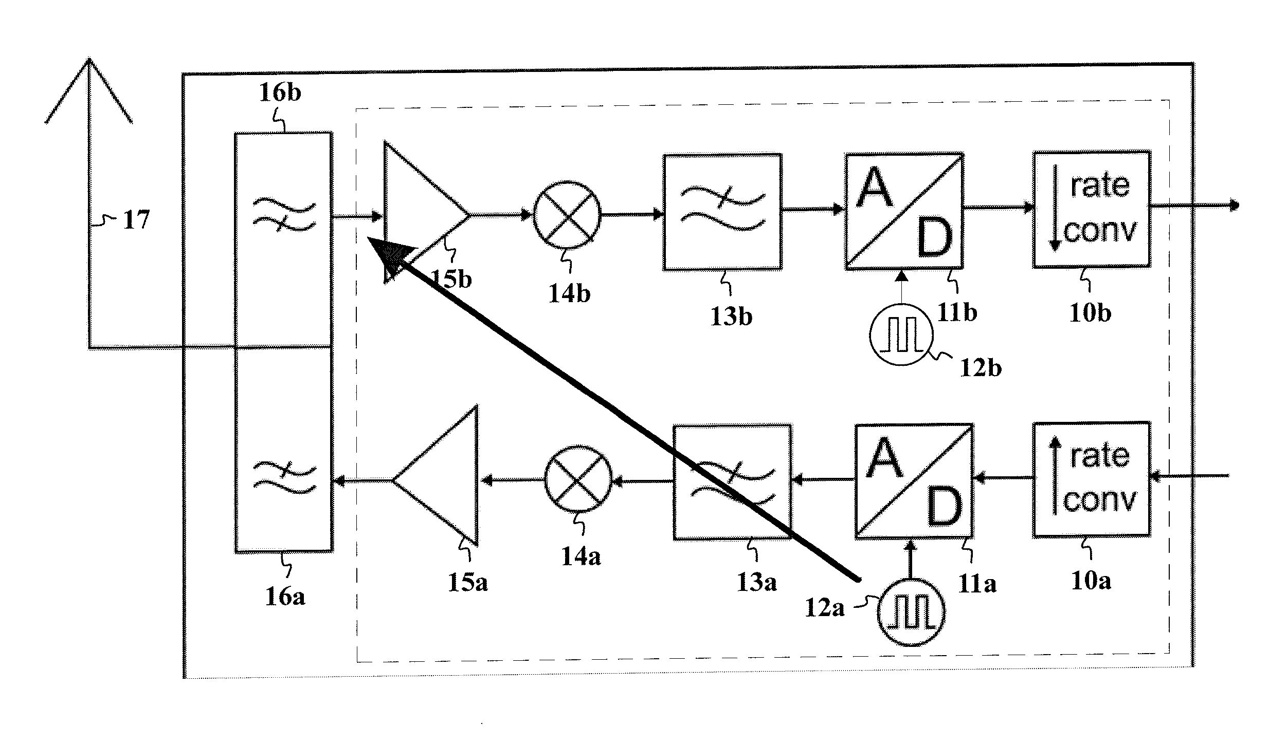
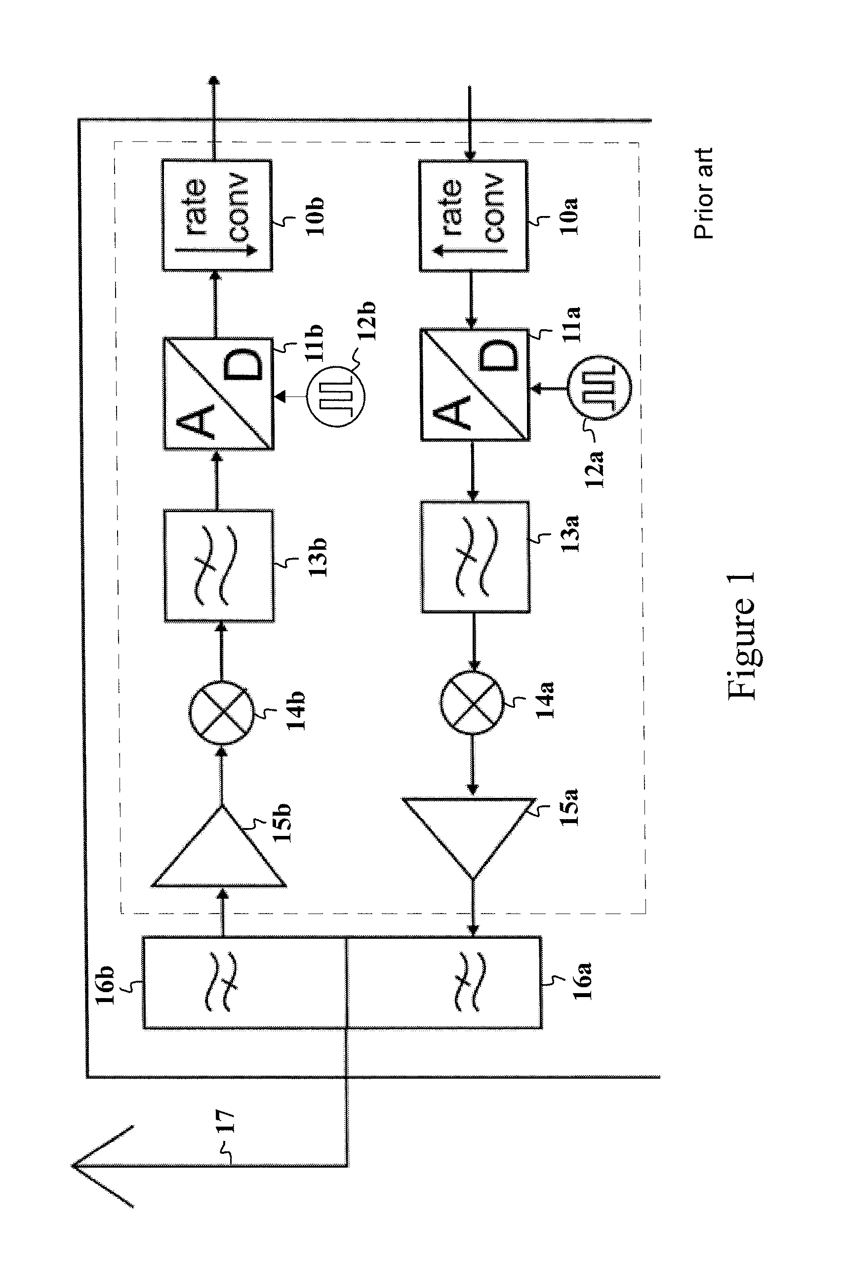
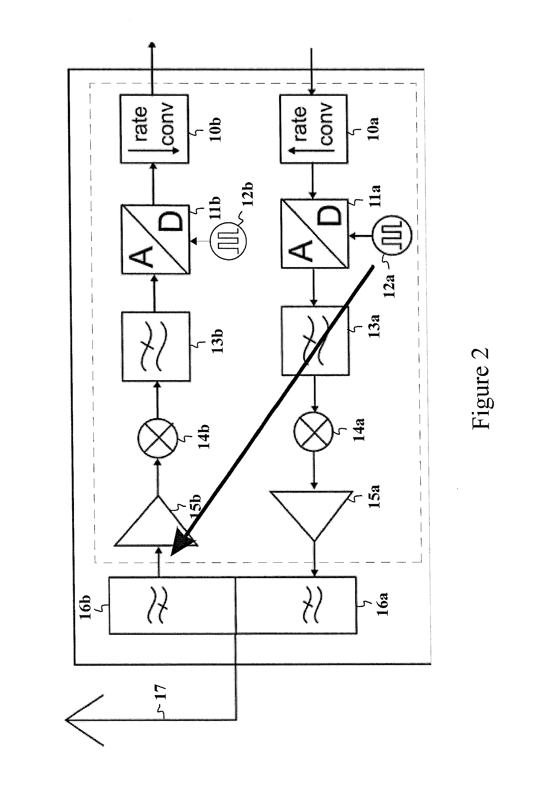
[0043]The present invention discusses a method and an apparatus for mitigating effects created by interferences originating from digital clocks in the transmitter. Especially, the invention applies to clock signal(s) which define the operation of the digital-to-analogue converter (DAC). Furthermore, any clock giving the input to ADCs or DACs in the transceiver or the clock for a sample rate converter in the transceiver, may be determined and its frequency may be reselected in order to mitigate the effect of interferential spurious tones in the receiver.

[0044]Digital clock signals comprise a fundamental frequency and also harmonic components at multiples of the fundamental frequency. The level of each harmonic component decreases as a function of an increasing order of the harmonic component. Because the receiver signal path contains h...


PUM


Abstract

The present invention presents a method and a system for mitigating effects of clock harmonics in the receiver. The receiving signal may be monitored in such a way that the interfering harmonic component is tracked. When the interfering frequency is found out, the system determines the clock or clocks in the transceiver which are contributing to the interfering spurious tone. After that, the contributing clock(s) frequency is selected so that the effect of the spurious tone in the receiving passband is minimized or mitigated. This is performed by selecting a suitable clock frequency resulting in the spurious tones all falling outside the receiver passband; or in an OFDM system, by choosing a clock frequency deriving the spurious tone straight onto a subcarrier signal frequency.

Description

BACKGROUND OF THE INVENTION[0001]1. Field of the Invention[0002]The present invention relates to mobile communication networks, and especially to interference mitigation for transceivers applying full-duplex radio transmission.[0003]2. Description of the Related Art[0004]Full duplex radio transceivers are capable of transmitting and receiving radio signals simultaneously. A general structure for a radio frequency (RF) transmitter and receiver has been shown in FIG. 1. These RF parts generally locate between a modem and a TX / RX antenna. Also, the RF parts may be formed in a radio frequency integrated circuit (RFIC) which is marked as the dashed box in FIG. 1, besides a duplex filter 16a-b. [0005]At first considering the receiving signal branch from an antenna 17, the received signal is directed to a duplex filter 16b having an appropriate predetermined bandwidth for the receiving signal. This weak signal is directed to an amplifier 15b. After the amplification the RF signal is down-c...

Claims


Application Information

Patent Timeline
Patent Type & Authority Applications(United States)
IPC IPC(8): H04B1/38
CPCH04B15/06
Inventor NENTWIG, MARKUS
Owner AVAGO TECH INT SALES PTE LTD
Why Eureka
Try Eureka