Method of processing and drying waste in a cyclic continuous process

Inactive Publication Date: 2013-01-24
DST DRYING SLUDGE TECH
View PDF0 Cites 7 Cited by
  • Summary
  • Abstract
  • Description
  • Claims
  • Application Information

AI Technical Summary

Benefits of technology

[0006]The dry waste coming out of the process will be readily available for disposal. The dry waste has more environmental and economical benefits: a] while being spread in agricultural fields it will redu

Problems solved by technology

The wastes are wet, in most cases, have undesired smell and pollute the ground and ground water by leached water from them.
One significant obstacle

Method used


Image

  • Method of processing and drying waste in a cyclic continuous process
  • Method of processing and drying waste in a cyclic continuous process
  • Method of processing and drying waste in a cyclic continuous process

Examples


Example

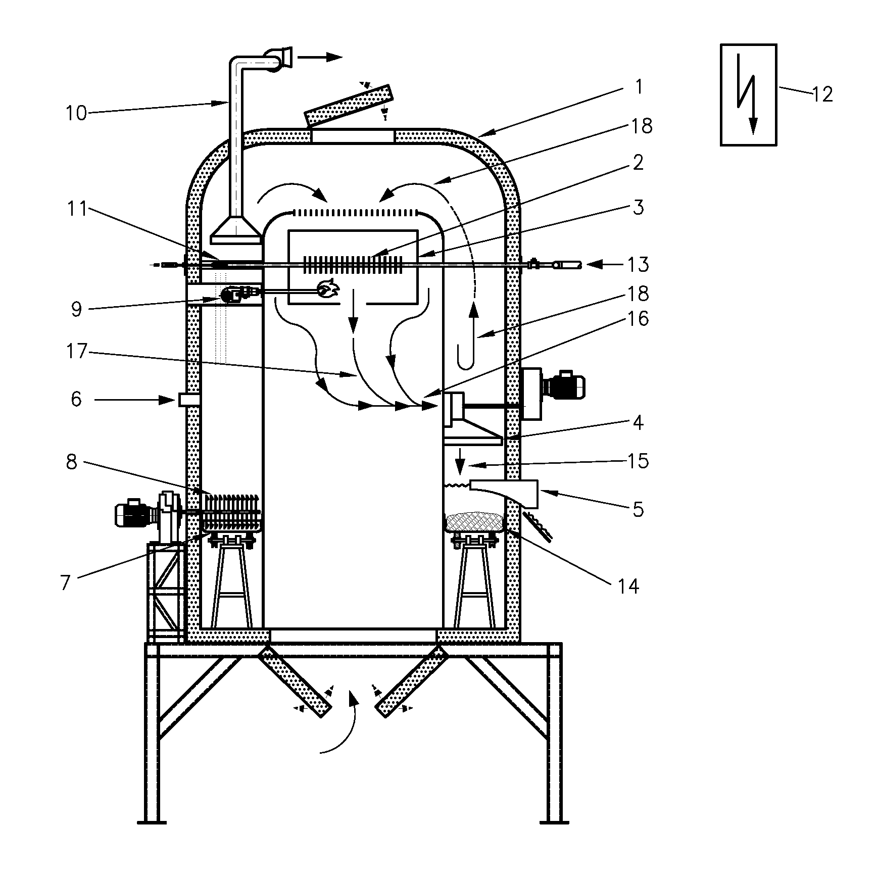
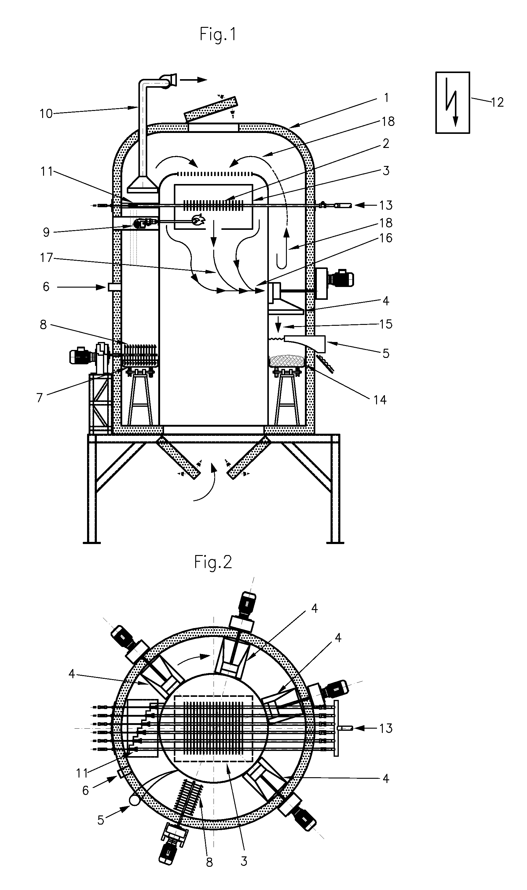
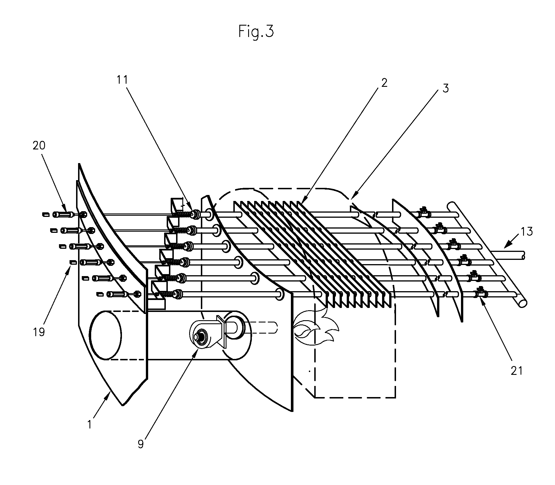
[0030]The invention will now be described by referring to the following none limiting figures. Turning to FIG. 1, there is described a cross section of the “cylinder in cylinder” insulated drying chamber. Wet sludge enters at pipe 13 at high pressure and continues into the burning chamber 3, where it is heated via direct flame burner 9, and with the aids of fins 2. high pressure and high temperature sludge leaves the burning chamber to the flushing diffuser 11, where the steam flushes out of the sludge into the ambient pressure. Flush steam 23 sucked out of the chamber via hood 10. The diffused sludge falls down onto the rotating 22 circular cavity bottom 7, on top of the dry sludge layer 14. While rotating, the sludge is exposed to hot 15 air jet generated at several blower units 4 with external motors. The, the air entering the blowers 16 is heated while passing through the outside of the burning chamber 3, utilizing the excess heat generated there and using the burned gases leavi...


PUM


Abstract

The present invention is directed to a device for drying waste in a continuous cyclic process. The invention is further directed to a method for drying waste in a continuous cyclic process in the device of the invention, wherein the raw waste entering the system is at a vast range of moisture contents between 99% and 75%.

Description

FIELD OF THE INVENTION[0001]This invention relates to a method and devices for drying waste in a closed loop cyclic continuous process.BACKGROUND OF THE INVENTION[0002]Wastes are separated as sludge from several waste streams among others: sludge from municipal waste water plants, industrial waste water, municipal solid waste [MSW], any kind of hazardous waste and manure from livestock production facilities. The wastes are wet, in most cases, have undesired smell and pollute the ground and ground water by leached water from them. The wastes may have nutrients good for agricultural crops, or other substances that may be recovered or recycled. The wastes need some biochemical and / or drying process to enable environmentally and economically disposal. The present disposal alternatives include among other spreading on agricultural fields, landfills and incineration. The organic wastes can be used as energy source, but need some biochemical and / or drying process to be used economically fo...

Claims


Application Information

Patent Timeline
IPC IPC(8): F26B7/00F26B19/00C02F11/13
CPCC02F11/12C02F2303/10C02F11/13Y02W10/30
Inventor MANOR, GEDALYAHUAMITAI, GADI
Owner DST DRYING SLUDGE TECH
Why Eureka
Try Eureka