Laser drilling methods of shallow-angled holes

a laser drilling and shallow angle technology, applied in the field of laser drilling, can solve the problems of excessive recast layer, consuming more than 60% of laser drilling energy, and unable to meet the needs of combustor components,

Inactive Publication Date: 2013-01-24
PRATT & WHITNEY CANADA CORP
View PDF25 Cites 10 Cited by
  • Summary
  • Abstract
  • Description
  • Claims
  • Application Information

AI Technical Summary

Benefits of technology

[0004]In one aspect, the described subject matter provides a method for providing a hole through a metal component having a base metal and thermal barrier coating layer applied to the base metal to form a top surface of the component, the hole having a central axis extending at an angle of 20 degrees or less with respect to the top surface, the method comprising a) laser trepanning substantially through the thermal barrier coating layer, said laser trepanning performed using a first laser pulse frequency; and then b) laser drilling through the base metal to complete the hole, said laser drilling performed at a second laser pulse frequency less than the first laser pulse frequency.

Problems solved by technology

Laser beam drilling of effusion holes in combustor components has confronted challenges.
Although a TBC layer is about 30% or less of, for example a heat shield thickness, it consumes more than 60% of the laser drilling energy, due to TBC properties such as heat resistance and poor thermal conductivity.
Laser pulse energy is utilized to enable drilling through the TBC layer, but that laser pulse energy is too high for drilling through the base metal under the TBC, which causes excessive recast layer.
This causes the intensity of the laser pulse to dissipate.
Furthermore, shallow holes with an angle to the surface equal to or less than 20 degrees, may cause relatively long cracks at the interface between the TBC and the base metal.
Coating cracks are the main contributor to TBC spallation and chipping which risk part scrap or reduced part life in gas turbine engines.

Method used


Image

  • Laser drilling methods of shallow-angled holes
  • Laser drilling methods of shallow-angled holes
  • Laser drilling methods of shallow-angled holes

Examples


Embodiment Construction

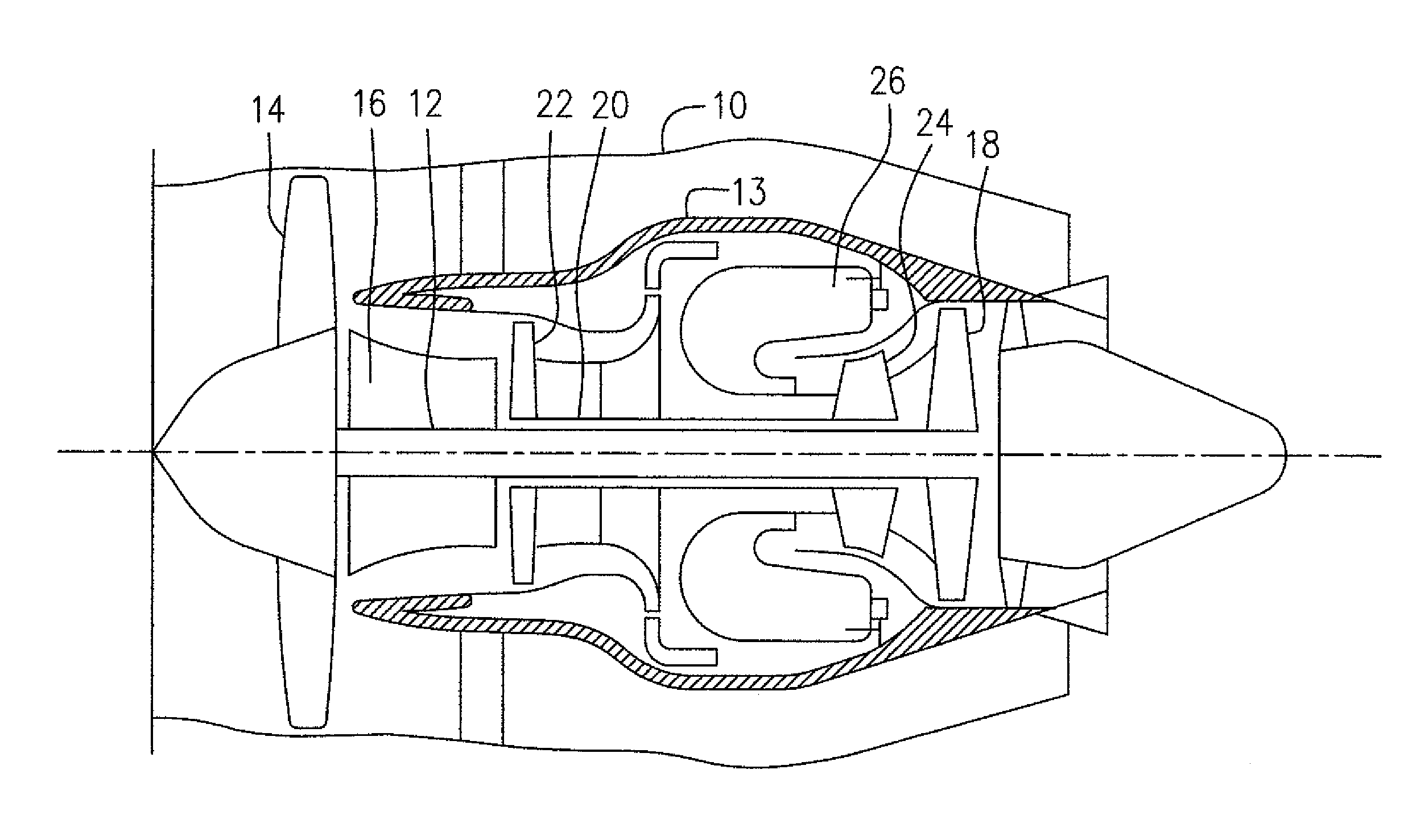
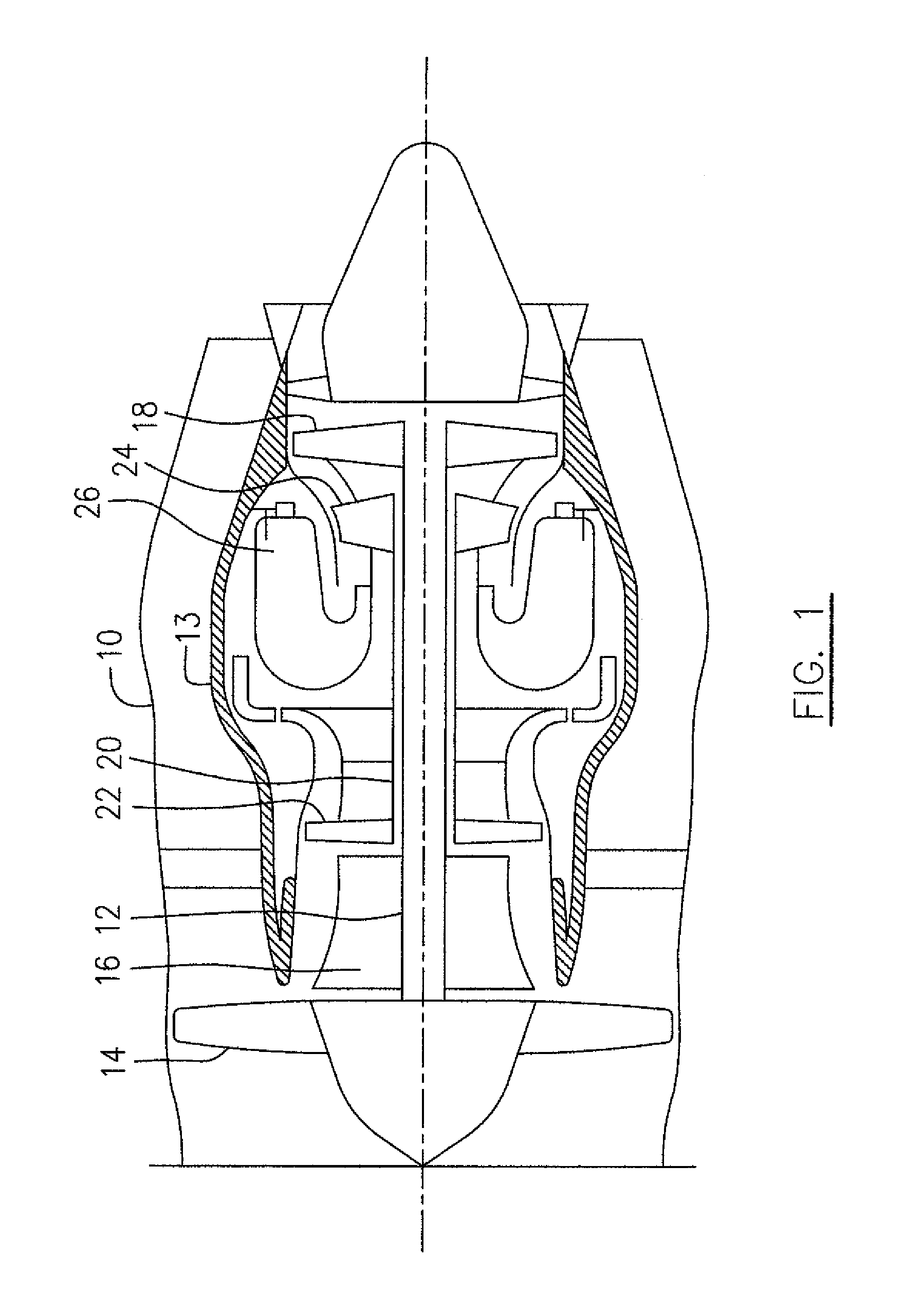
[0029]FIG. 1 illustrates a gas turbine engine as an example of the application of the described subject matter, which includes a housing or nacelle 10, a core casing 13, a low pressure spool assembly seen generally at 12 which includes a fan assembly 14, a low pressure compressor assembly 16 and a low pressure turbine assembly 18 and a high pressure spool assembly seen generally at 20 which includes a high pressure compressor assembly 22 and a high pressure turbine assembly 24. The core casing 13 surrounds the low and high pressure spool assemblies 12 an 20 in order to define a main fluid path (not numbered) therethrough including a combustor 26.

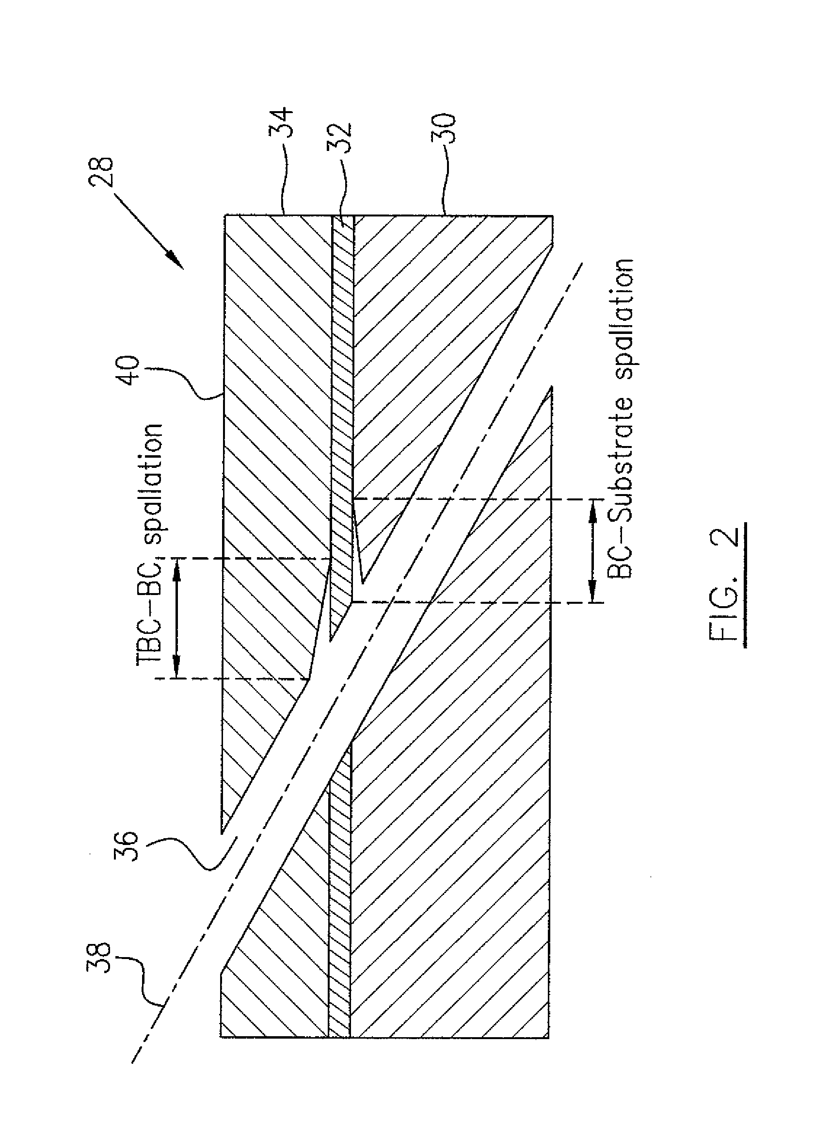
[0030]The combustor 26 includes various combustor components such as liners, heat shields, etc. One combustor component 28 is shown in FIG. 2 which includes a base metal 30, as a substrate, coated with a thermal barrier coating (TBC) 34 attached thereto. The thermal barrier coating 34 and the base metal 30 are secured together, for example b...


PUM

PropertyMeasurementUnit
angleaaaaaaaaaa
pressureaaaaaaaaaa
pulse frequency rateaaaaaaaaaa

Abstract

A method for providing a shallow-angled hole through a metal component, such as a turbine combustor, includes a step of applying a pulse laser beam to drill a section of the hole substantially within a thermal barrier coating of the component in a trepanning concept. A further step is conducted to apply the pulse laser beam through the completed section of the hole to further drill through a base metal of the component to complete the formation of the hole extending through the component.

Description

TECHNICAL FIELD[0001]The described subject matter relates generally to laser drilling, and more particularly to providing shallow-angled holes in coated components.BACKGROUND OF THE ART[0002]Combustors of gas turbine engines are subjected to high temperatures and effusion holes can be used to direct air to cool combustor components such as combustor liner, dome and heat shield. Effusion holes extend through the component at a shallow angle with respect to the surface of the component, for efficiently cooling without risking a reduction in combustion temperature. Laser beam drilling of effusion holes in combustor components has confronted challenges. A combustor component is coated with a thermal barrier coating (TBC). Although a TBC layer is about 30% or less of, for example a heat shield thickness, it consumes more than 60% of the laser drilling energy, due to TBC properties such as heat resistance and poor thermal conductivity. Laser pulse energy is utilized to enable drilling thr...

Claims


Application Information

Patent Timeline
Patent Type & Authority Applications(United States)
IPC IPC(8): B23K26/38
CPCB23K26/386B23K2201/001B23K26/388B23K26/389B23K2101/001B23K26/0622B23K26/38
Inventor ELFIZY, AMRHARDY, GHISLAINCOURNOYER, SYLVAIN
Owner PRATT & WHITNEY CANADA CORP
Why Eureka
Try Eureka