Ocular optical system

a technology of optical system and optical lens, applied in the field of ocular optical system, can solve the problems of high-order aberration in the wavefront of transmitted light, and the inability to condensate the spot on the retina to a desired diameter, so as to reduce the deviation of the incident position

Active Publication Date: 2013-01-24
CANON KK
View PDF3 Cites 12 Cited by
  • Summary
  • Abstract
  • Description
  • Claims
  • Application Information

AI Technical Summary

Benefits of technology

[0009]According to the present invention, an optical unit is provided which is disposed at a position of an intermediate image, which is optically conjugate to the fundus, and has a surface having different optical powers corresponding to scan directions of the two scanning units. Thus, it is possible to reduce the deviation of the incident position of the measuring beam in the anterior ocular segment due to that one of two scanning units disposed close to each other is disposed at a position conjugate to the anterior ocular segment while another scanning unit is not located at the position conjugate to the anterior ocular segment.
[0010]Further features of the present invention will become apparent from the following description of exemplary embodiments with reference to the attached drawings.

Problems solved by technology

However, curved surface shapes and refractive index homogeneity of cornea and lens that perform the refracting action in an eyeball are not complete, which causes high order aberration in a wavefront of the transmitted light.
Therefore, even if a thick beam enters, the spot on the retina cannot be condensed to a desired diameter and, on the contrary, is expanded.

Method used


Image

  • Ocular optical system
  • Ocular optical system
  • Ocular optical system

Examples


first embodiment

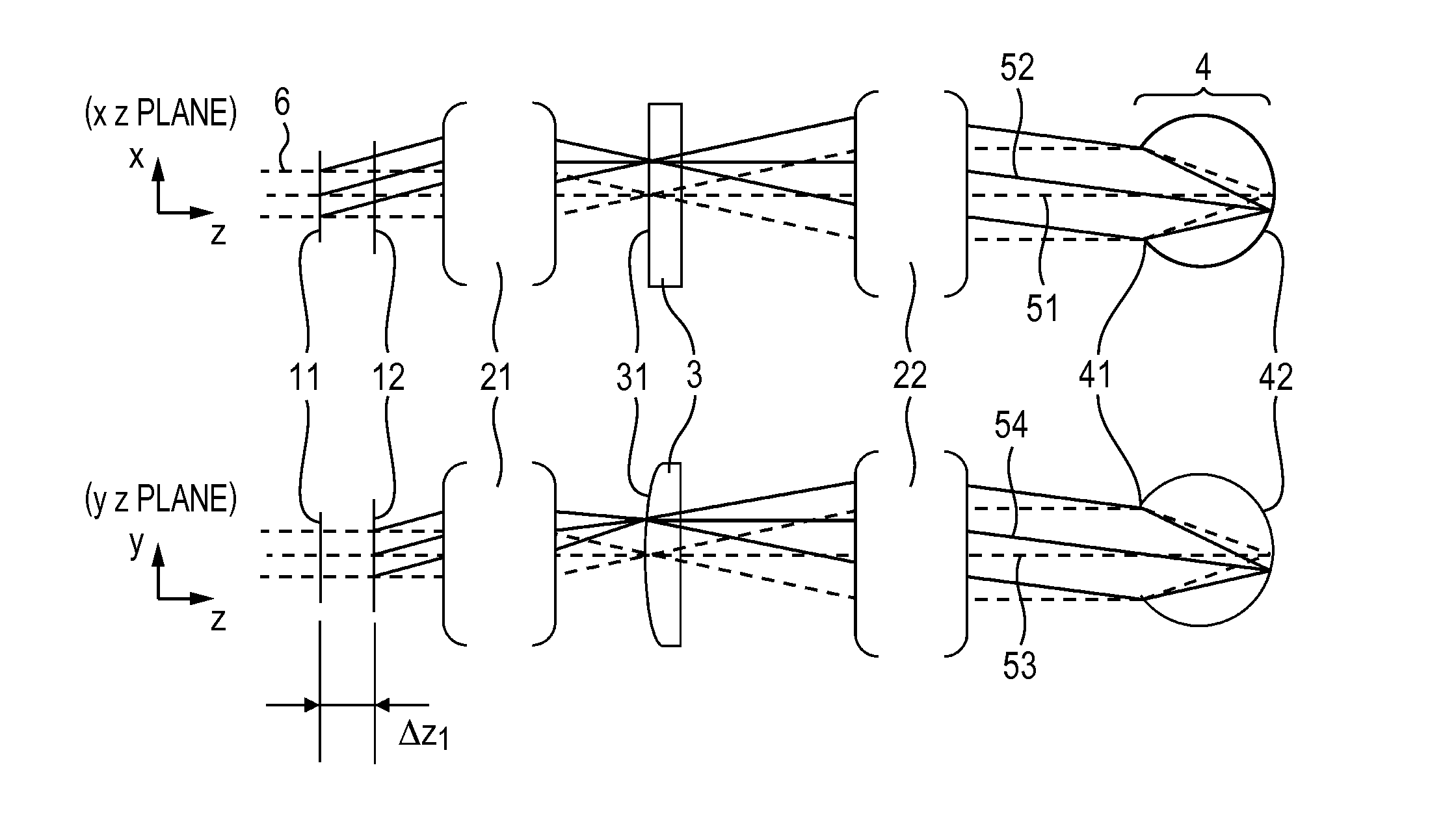
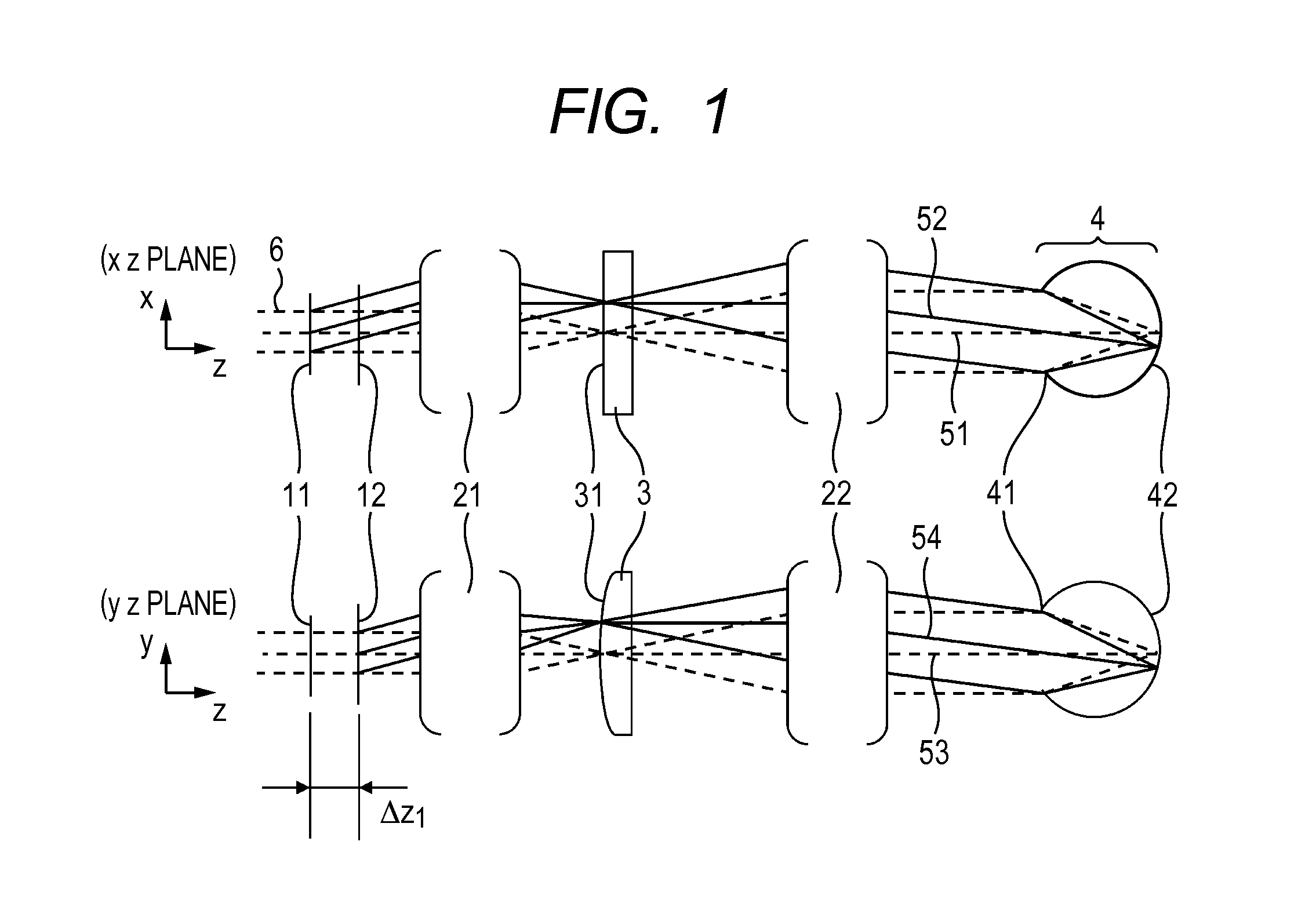
[0031]FIG. 1 illustrates a cross section of an ocular optical system according to this embodiment. A beam 6 that is emitted from a light source (not shown) and is collimated is deflected in two-dimensional direction by two one-dimensional scanner mirrors 11 and 12 (corresponding to one-dimensional beam scanning units in the embodiments) disposed close to each other, and is led to an iris 41 of an eyeball 4 by an ocular optical system 2. Here, the sentence “two one-dimensional scanners 11 and 12 are disposed close to each other” in this embodiment means that the two one-dimensional scanners 11 and 12 are disposed close to each other without operational interference therebetween. The sentence also includes the case where there is no optical element having an optical power between the two one-dimensional scanners 11 and 12, and the two one-dimensional scanners 11 and 12 are disposed at such a distance that the shift amount described above can be compensated by a cylindrical lens that i...

second embodiment

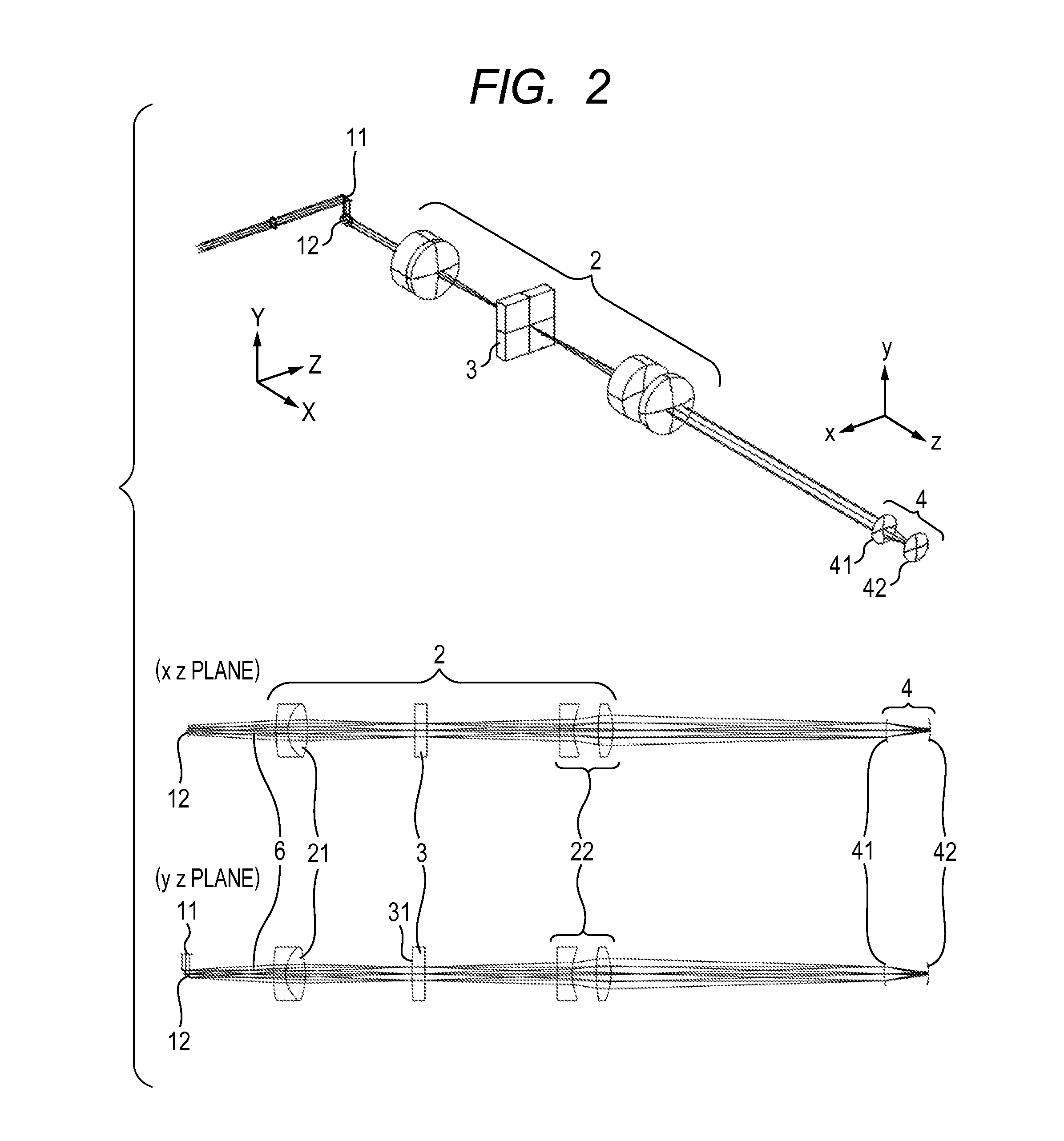
[0047]Next, a second embodiment is described below in the case where a scan type retinal inspection instrument is supposed, which measures reflection light from the retina. In the case of the structure illustrated in FIG. 2, the cylindrical surface 31 has a relationship nearly optically conjugate to the retina 42. When the beam 6 passes along the optical axis, the reflection light from this cylindrical surface 31 is also detected. The reflectance of the retina is approximately 10−3%. Therefore, the reflected and the backscattering light is very weak while the reflectance of the lens surface is actually a little lower than 0.1% even if an antireflection coating is formed. Therefore, the intensity of undesired reflection light from the lens is much higher. Therefore, when the beam is scanned in a two-dimensional manner so as to form an image, the undesired reflection light causes a strong ghost image to be a serious image failure.

[0048]Therefore, in this embodiment, as illustrated in ...

third embodiment

[0052]A third embodiment is described with reference to FIG. 7. As described above, when a thick beam enters so as to form a spot diameter that is as small as a few microns on the retina, the spot is disturbed by aberration of the eyeball optical system so that a desired condensing state cannot be obtained. Therefore, it is necessary to use a compensation optical system. In this case, it is well known that an inconvenience occurs in a transparent type coaxial optical system using lenses in the type where the light irradiating the retina for obtaining an image is also used as irradiation light for measuring the wavefront. This is because that in the case where a Shack-Hartmann type wavefront sensor is used as the wavefront detector, for example, not only the reflected and backscattering light from the retina but also reflection light from each lens surface enter the wavefront sensor as undesired light. As described above, the reflection light from the lens surface has much larger int...


PUM


Abstract

Provided is an ocular optical system, which permits a measuring beam scanned by two scanning units disposed close to each other to enter an anterior ocular segment of an eye to be inspected and to irradiate a fundus. The ocular optical system includes an optical unit which is disposed at a position of an intermediate image, which is optically conjugate to the fundus, and has a surface having different optical powers corresponding to scan directions of the two scanning units.

Description

TECHNICAL FIELD[0001]The present invention relates to an ocular optical system, and particularly to an ocular optical system of an apparatus for taking an image of an eye retina.BACKGROUND ART[0002]As an ophthalmologic apparatus for examining an eye retina, there is known a scanning laser ophthalmoscope (SLO) which obtains a two-dimensional image of a retina as a plane. In addition, there is also known an optical coherence tomography (OCT) which obtains a tomographic image of a retina in a noninvasive manner. Those apparatuses have been put into practical use for a long time. Those apparatuses scan a retina by a light beam in a two-dimensional manner using a deflector, and synchronously measure reflected and backscattering light so as to obtain a two-dimensional image or a three-dimensional image of the retina.[0003]Spatial resolution of the obtained image in a plane direction (lateral direction) of the retina (hereinafter, referred to as lateral resolution) is determined basically ...

Claims


Application Information

Patent Timeline
Patent Type & Authority Applications(United States)
IPC IPC(8): A61B3/12
CPCA61B3/12
Inventor SAITO, KENICHI
Owner CANON KK
Why Eureka
Try Eureka