Insertion needle
- Summary
- Abstract
- Description
- Claims
- Application Information
AI Technical Summary
Benefits of technology
Problems solved by technology
Method used
Image
Examples
embodiment 1
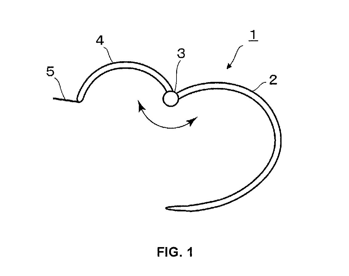
[0041]As shown in FIG. 1, an insertion needle 1 of the present invention integrally comprises an insertion needle main body 2 that has a prescribed curved portion, an arm 4 that is attached via a pivot 3 provided on the base of the main body 2, and a target site 5 that is provided on the tip of the arm 4; and the insertion needle main body 2 and arm 4 turn with the pivot 3 as the center so that the tip of the insertion needle main body 2 is reliably guided to the target site 5.
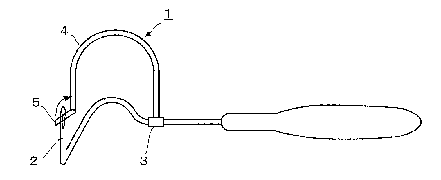
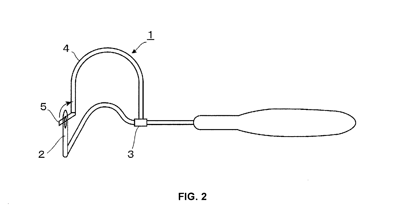
[0042]FIG. 2 shows another embodiment of the insertion needle of FIG. 1. The insertion needle 1 shown in the drawing is such that the insertion needle main body 2 has a curved shape, and the far-sighted needle main body 2 turns so as to contact or be inserted into the target site 5, which is provided on the tip of the arm 4 that is attached via the pivot 3.
[0043]FIGS. 3(a) and 3(b) show the shape of the target site 5; FIG. 3 (a) shows a ring type, and FIG. 3 (b) shows a V-shape type. As shown in the drawing, a...
embodiment 2
[0048]Next, pelvic organ prolapse surgery (TVM surgery) using the insertion needle of this invention is described in accordance with FIGS. 6(a) to 6(b) to FIG. 9. TVM surgery supports pelvic organs, such as the uterus or bladder, with a polypropylene mesh in a hammock shape such that the prolapse of pelvic organs from the vagina is prevented, and reinforces the vaginal anterior or the vaginal posterior with the mesh, by way of known surgical methods indicated in the abovementioned JP-2006-506104-A or the like.
[0049]FIGS. 6(a) and 6(b) show the insertion state during reinforcement of the anterior vaginal wall by way of conventional TVM surgery; FIG. 6(a) shows the situation where an insertion needle 20 is inserted through the obturator foramen; and FIG. 6(b) shows the situation where the tip of the insertion needle 20 is blindly guided to the finger of the surgeon. Furthermore. FIGS. 7(a) and 7(b) show the insertion state during reinforcement of the anterior vaginal wall by way of TV...
embodiment 3
[0054]FIGS. 10(a), 10(b) and 10(c) show another embodiment of the insertion needle of FIG. 9; FIGS. 10(a) to 10(c) show the process for passing the thread 25 through. As shown in the drawing, a groove 29 is provided longitudinally at a prescribed depth on a base 28 of the insertion needle 1. Moreover, a hole 30 is made in a prescribed location on the groove 29, the thread 25 can be passed through between the hole 30 and the through-hole 24 that is closer to the base end. With a view to passing the thread 25 through the insertion needle 1, the thread 25 is passed through to the hole 30 from the base end along the groove 29, and then is further pulled from one side of the through-hole 24 that is closer to the base end. Next, the thread 25 is inserted into the through-hole 24 on the tip end and is extended to the base end of the insertion needle 1, then this is pulled from the hole 30 after being inserted through the other side of the through-hole 24 that is closer to the tip end, and ...
PUM
 Abstract
Description
Claims
Application Information
 - R&D
- Intellectual Property
- Life Sciences
- Materials
- Tech Scout
- Unparalleled Data Quality
- Higher Quality Content
- 60% Fewer Hallucinations
Browse by: Latest US Patents, China's latest patents, Technical Efficacy Thesaurus, Application Domain, Technology Topic, Popular Technical Reports.
© 2025 PatSnap. All rights reserved.Legal|Privacy policy|Modern Slavery Act Transparency Statement|Sitemap|About US| Contact US: help@patsnap.com


