Copper column and process for producing same

a technology of copper column and copper plate, applied in the field of copper column, can solve the problems of high reliability, cracking and fracture at the joints between, and heat stress cannot be absorbed

Active Publication Date: 2013-01-31
SENJU METAL IND CO LTD
View PDF9 Cites 13 Cited by
  • Summary
  • Abstract
  • Description
  • Claims
  • Application Information

AI Technical Summary

Benefits of technology

[0033]According to the copper column of the present invention, because the heat stress caused by the difference between the thermal expansion of the ceramic substrate and the thermal expansion of the glass epoxy substrate is absorbed, the joint between the ceramic substrate and the glass epoxy substrate can be prevented from the destruction.
[0034]According to the copper column manufacturing method of the present invention, si...

Problems solved by technology

Especially, the CBGA is apt to be used for super computers and the like and it requires high reliability.
Further, since the column connects the ceramic substrate to the glass epoxy substrate, if the column is hard, the above-described heat stress may cause crack and fracture at joints between the ceramic substrate and the column, joints be...

Method used


Image

  • Copper column and process for producing same
  • Copper column and process for producing same
  • Copper column and process for producing same

Examples


example 1

Executed Example 1

[0076]A concrete manufacturing method of the copper column according to this invention, the copper column manufactured by this method, and the copper structure and crystal grains of the copper column before the annealing step in this executed example will be discussed.

[0077]The copper column of the present invention was manufactured by the following processes (1) through (7).

(1) The linearly-shaped copper wire consisting of oxygen-free copper and having a diameter of 6 mm was struck at its side surface and was passed through a die for wiredrawing it to a diameter of 2.6 mm.

(2) The wiredrawn copper wire having the diameter of 2.6 mm was further struck at its side surface and was passed through the die for wiredrawing it to a diameter of 0.25 mm.

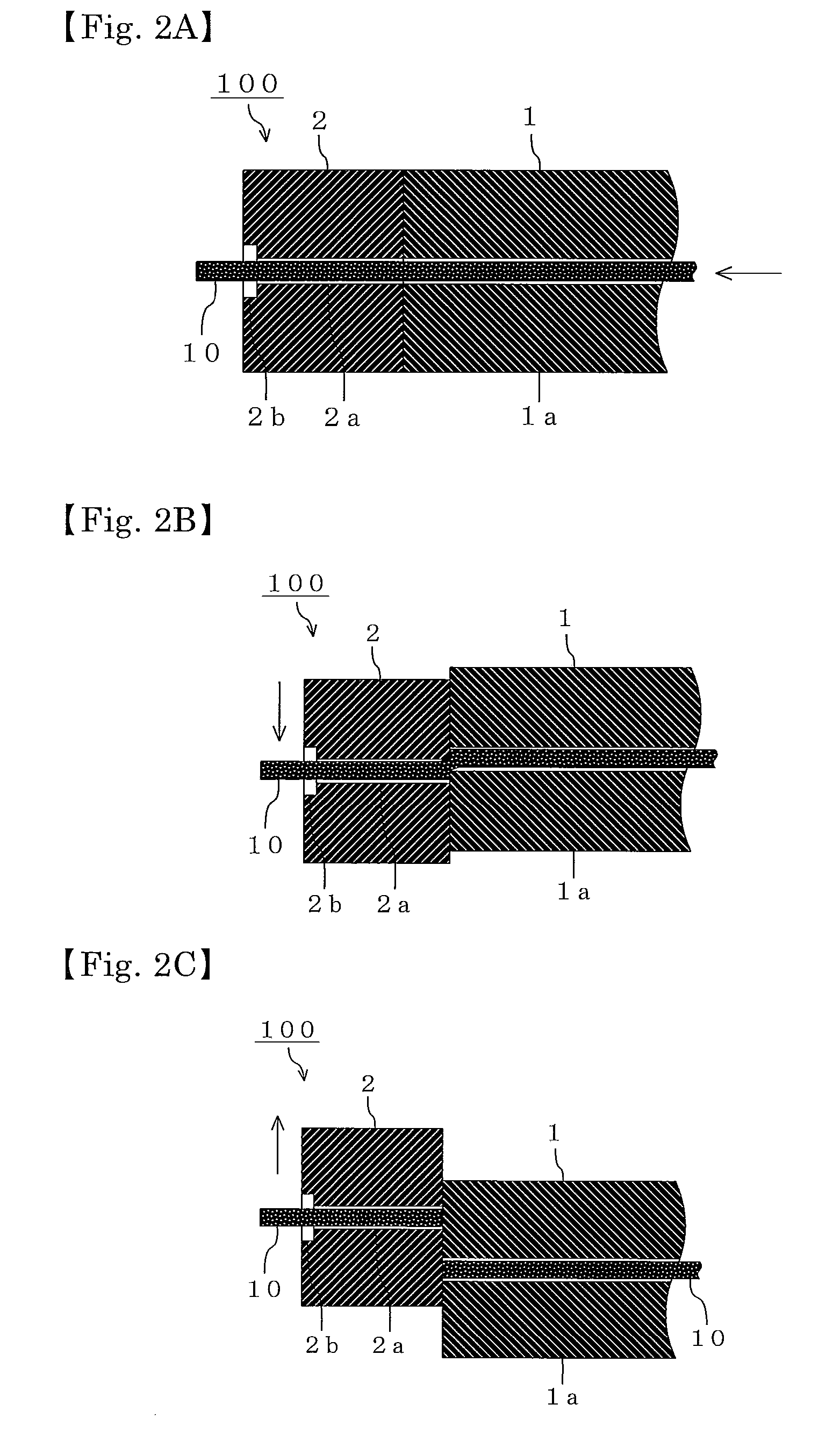
(3) As shown in FIGS. 2A, 2B, 2C, 3A, 3B and 3C, the copper wire, which had been wiredrawn to the diameter of 0.25 mm, was cut into a length of 1.941 mm, one end of the cut copper wire was pressed by a hammer in order to form...

example 2

Executed Example 2

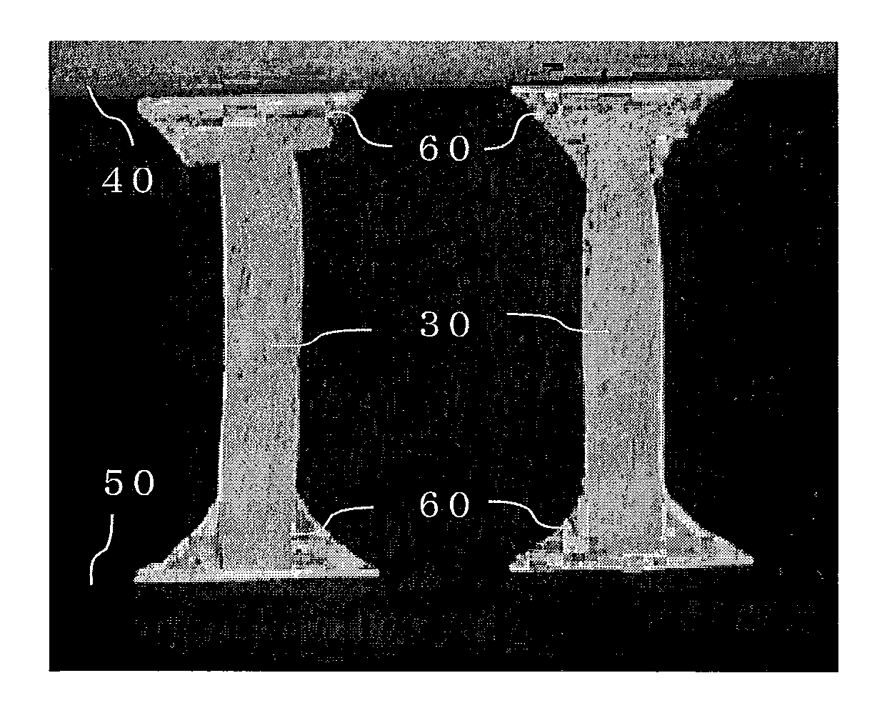
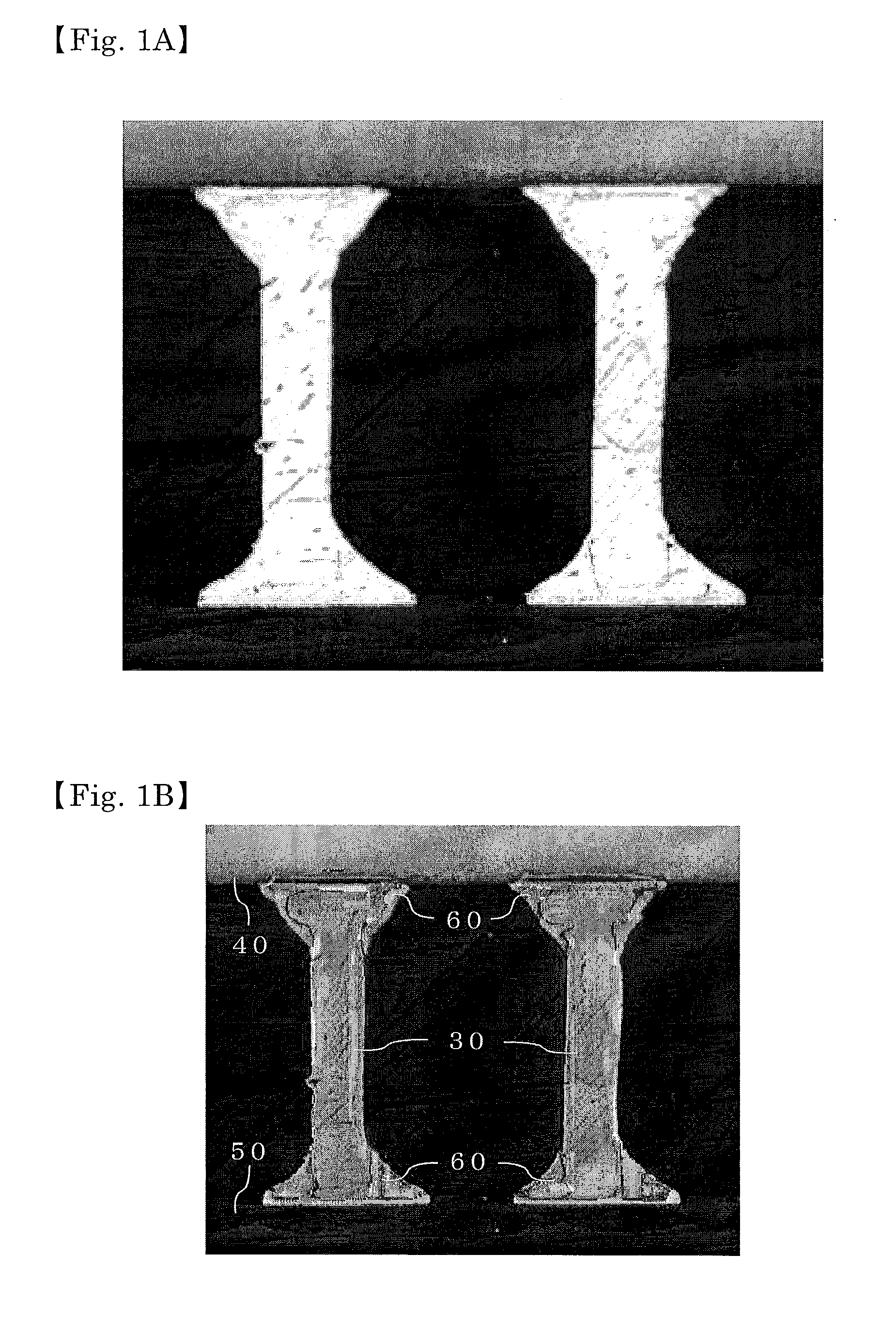
[0080]In this executed example, a thermal cycle test result of the copper column according to the present invention (hereinafter referred to as “copper column of this executed example”) and a pin manufactured by the manufacturing method discussed in Patent Document 2 (hereinafter referred to as “pin of the comparison example”) will be described.

[0081]A CGA was formed by connecting 961 copper columns of this executed example to the ceramic substrate through solder paste. This CGA was mounted on the glass epoxy substrate through the solder paste (hereinafter referred to as “CGA of this executed example”). Similarly, 961 pins of the comparison example were connected to the ceramic substrate through the solder paste to form a CGA and the formed CGA was mounted on the glass epoxy substrate through the solder paste (hereinafter referred to “CGA of the comparison example”).

[0082]By putting the CGA of this executed example and the CGA of the comparison example in a heat cy...


PUM

PropertyMeasurementUnit
Temperatureaaaaaaaaaa
Vickers hardnessaaaaaaaaaa
Temperatureaaaaaaaaaa

Abstract

To prevent the breakage of the joint between a ceramic substrate and a glass epoxy substrate.
The copper column is formed by a wiredrawing step for drawing a copper wire formed linearly to a predetermined diameter; a cutting step for cutting the copper wire, which has been drawn in the wire drawing step, in a predetermined length; a pressing step for pressing one end of the copper wire, which has been cut in the cutting step, in a longitudinal direction to form a copper column member; and an annealing step for annealing the copper column member, which has been formed in the pressing step, by maintaining a heating period of 60 minutes or longer at 600° C. or higher. Thereby, the Vickers hardness of the copper column becomes is 55 HV or less and the copper column is softened. Therefore, when joining the ceramic substrate and the glass epoxy substrate through the copper column, heat stress caused by a difference between the thermal expansion of the ceramic substrate and the thermal expansion of the glass epoxy substrate can be absorbed by the copper member. As a result, the breakage of the joint between the ceramic substrate and the glass epoxy substrate can be prevented.

Description

TECHNICAL FIELD[0001]The present invention relates to a copper column for joining a ceramic substrate and a glass epoxy substrate and to a method for manufacturing thereof.BACKGROUND[0002]Nowadays, along with communication speed-up of communication equipment and density growth of integrated circuits, there is a trend toward the increasing number of lead wires for electronics parts used for them. For example, there are conventional electronics parts having a lot of lead wires, such as QFP (Quad Flat Package), SOIC (Small Outline Integrated Circuit), etc.; however, in recent electronics parts having further multiple functions, such QFP and SOIC, etc. more number of lead wires is needed. Then, BGA (Ball Grid Array) becomes to be used as an electronics part having increased number of lead wires. There are many kinds of BGAs, such as PBGA (Plastic Ball Grid Array), TBGA (Tape Ball Grid Array), CBGA (Ceramic Ball Grid Array) etc. Especially, the CBGA is apt to be used for super computers ...

Claims


Application Information

Patent Timeline
IPC IPC(8): H05K3/00H05K1/09
CPCB21K1/463H01L2924/01078H01L2924/00014H01L21/4846H01L2924/0105H01L2924/09701H01L23/49811H01L24/11H01L2924/01004H01L2924/01058Y10T29/49124H01L2924/01327H01L2924/01005Y10T428/24926B21J15/02H01L2924/01033H01L2924/01006H01L2924/01082H01L2224/45147B21J15/147H01L2224/13147H01L2924/01083H01L2924/014H01L2924/01029H01L2924/00H01L2224/48H01L2924/00011H01L2924/351H01L2924/15787H01L2924/207H01L2924/14H01L2224/13017H01L2924/0002
Inventor CHIBA, YUTAKANOMOTO, SHINICHIWATANABE, KOJI
Owner SENJU METAL IND CO LTD
Why Eureka
Try Eureka