Photo-electrochemical cell

Inactive Publication Date: 2013-01-31
KATHOLIEKE UNIV LEUVEN
View PDF10 Cites 74 Cited by
  • Summary
  • Abstract
  • Description
  • Claims
  • Application Information

AI Technical Summary

Benefits of technology

[0032]If the above described photo-electrochemical cells or photo-electrochemical systems are operation then the second photocatalyst electrode or electrodes function as cathode and CO2 reduction occurs at such irradiated cathode by means of a photocatalytic reaction in particular embodiments such as CO2 reduction occurs at the cathode by means of a phot

Problems solved by technology

The conversion of CO2 into useful chemicals is a long-standing issue.
Though many solutions are proposed, the yield of the produced chemicals is still too low and too diverse.
The main obsta

Method used


Image

  • Photo-electrochemical cell
  • Photo-electrochemical cell
  • Photo-electrochemical cell

Examples


example 1

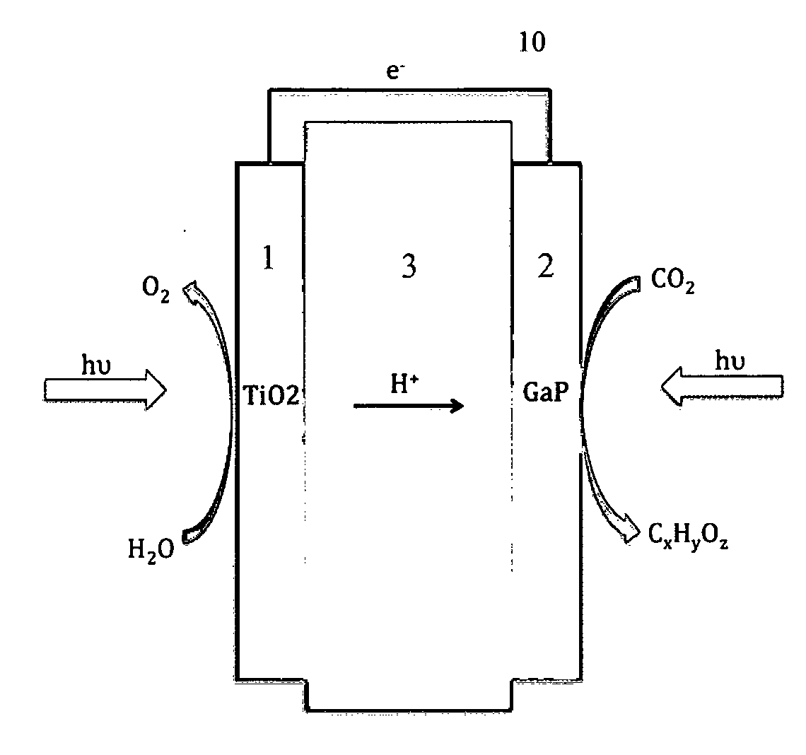
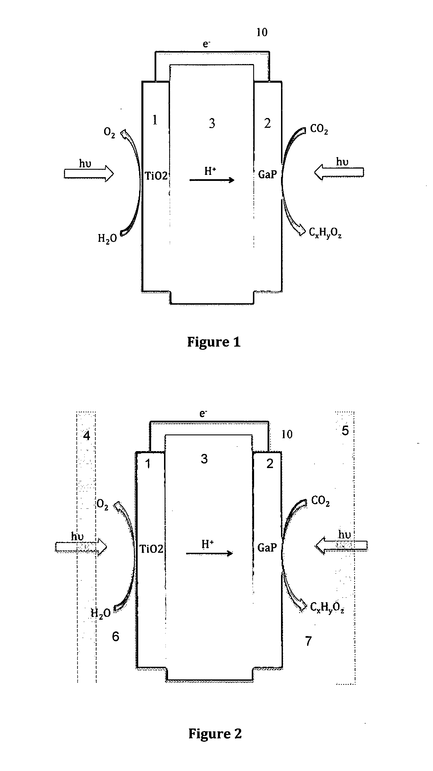
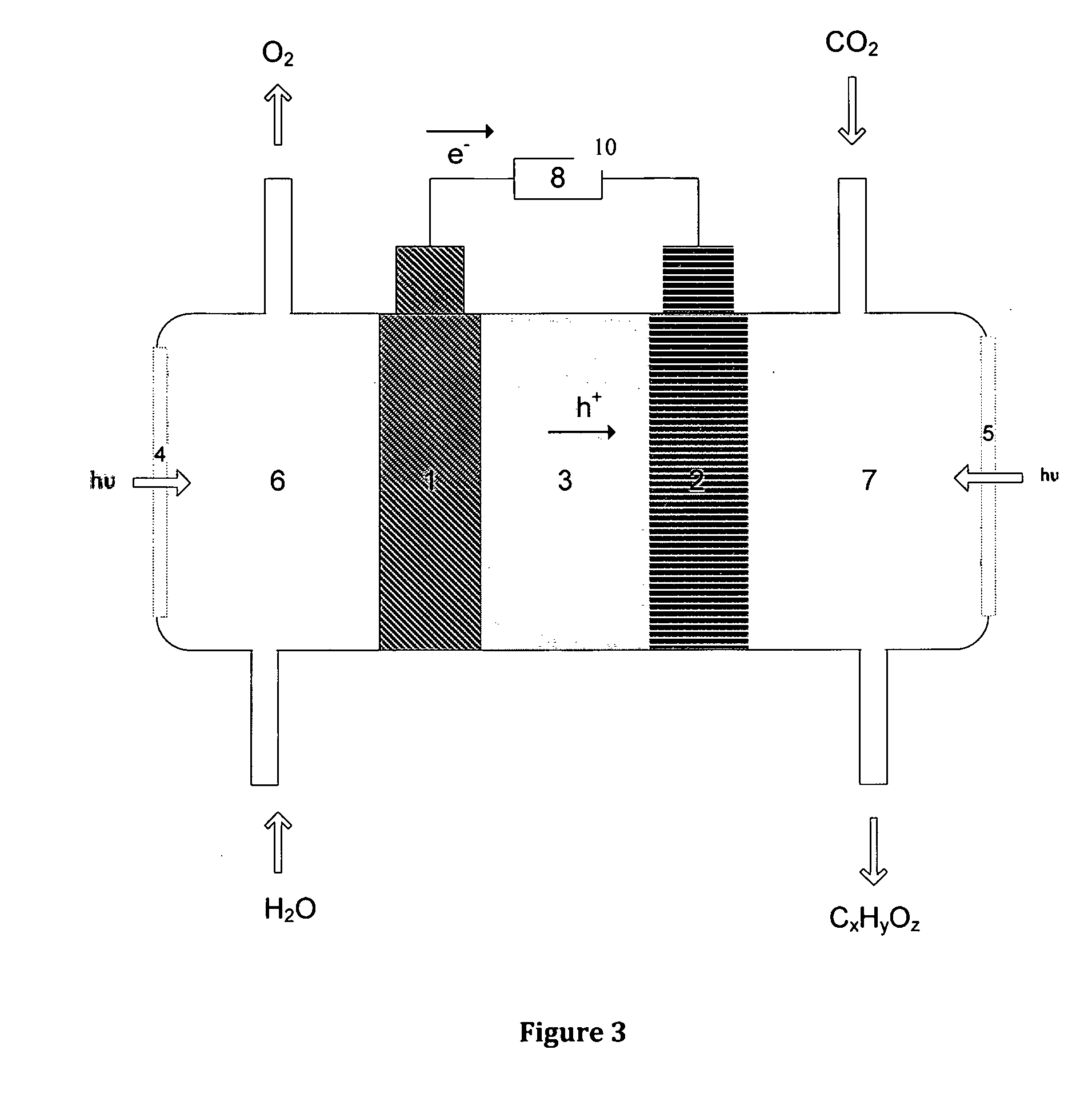
[0050]The photo-electrochemical cell, system or method for conversion of light and air into chemicals and, more particularly to a system which comprises the fowling steps and elements:

1.a. The Electrodes at Both Anode and Cathode

[0051]The electrode consists out of carbon cloth or Toray paper in some cases coated with graphene sheets. The graphene sheets deposited on carbon cloth / Toray paper by means of RF-CVD or MW-CVD can be made e.g. according to a method of Wang, J. J. et al. (2004) Carbon, 42(14): 2867-2872 or Zhao, X et al. Journal of Power Sources, Volume 194, Issue 2, December 2009, Pages 1208-1212.

[0052]The cell comprises the use of glass windows with a transparent serpentine flow profile, similar to those encountered in H2 / O2 fuel cells, custom made by for example Safir Puurs.

1.b. Photo-Oxidation

[0053]The photo-catalytic oxidation reaction will occur initially on a catalytic substrate based on titanium dioxide in the form of nanoparticles (such as TiO2, P25 grade, Degussa)....


PUM

PropertyMeasurementUnit
Thicknessaaaaaaaaaa
Photocatalytic propertiesaaaaaaaaaa
Electric chargeaaaaaaaaaa

Abstract

CO2 conversation into organic molecules is based on the photo-oxidation of water into oxygen gas O2, protons H+, and electrons. The conversion of CO2 occurs at the photo-cathode and involves the generated protons, electrons and the “fuel” CO2.

Description

BACKGROUND OF THE INVENTION[0001]A. Field of the Invention[0002]Present invention concerns a dual function photo-electrochemical cell for conversion of light and streams of moistened gas and carbon dioxide containing gas (e.g. air) into organic compounds such as useful alcohol or hydrocarbon chemicals or fuels. This dual function photo-electrochemical cell is characterized in that the cell comprises a multifunctional photocatalytic system with a first anode photocatalyst unit (6) to photo-oxidize water of the moistened gas into oxygen which first anode photocatalyst electrode (1) is by a charge transport means (3) to transport of the electrons and protons to the cathode in contact with or associated with a cathodic photocatalyst electrode (2) of a second photocatalytical unit (7) to reduce CO2 which cell is further characterized in that it comprises at least one radiation means (4)—for radiation of the photocatalyst (1) of the first unit (6) and at least one radiation means (5)—for ...

Claims


Application Information

Patent Timeline
IPC IPC(8): C25B9/18C25B15/02B82Y30/00C25B3/25
CPCB01J14/005B01J19/087B01J19/123B01J19/127B01J19/2475C25B1/003C01B13/0207C10G2/50C25B3/04Y02E60/364C01B3/042Y02E60/36Y02P20/133C25B3/25C25B1/55
Inventor KAYAERT, SAMMARTENS, JOHANMASSCHAELE, KASPER
Owner KATHOLIEKE UNIV LEUVEN
Why Eureka
Try Eureka