Shell of pressure-resistant container, pressure-resistant container, and exploratory apparatus

a technology of shell and container, applied in the direction of vessel construction details, transportation and packaging, underwater equipment, etc., can solve the problems of increased production cost, and achieve the effect of reducing the risk of cracking, and increasing the tolerance to the maximum principal stress and the minimum principal stress

Inactive Publication Date: 2013-01-31
JAPAN AGENCY FOR MARINE-EARTH SCIENCE AND TECHNOLOGY +1
View PDF2 Cites 17 Cited by
  • Summary
  • Abstract
  • Description
  • Claims
  • Application Information

AI Technical Summary

Benefits of technology

[0020]According to the invention, in the shell of a pressure-resistant container, the through hole is formed in the thick-walled portion. In this case, in contrast to a case where the through hole is not formed in the thick-walled portion, even with stress concentration which occurs around the through hole due to application of external pressure, the tolerance to the maximum principal stress and the minimum principal stress can be increased. Accordingly, the pressure-resistant container can be made higher in strength, is able to withstand concentration of compressive stress on the area around the through hole, and is less likely to suffer from cracking.
[0021]Moreover, the shell of the pressure-resistant container, being made of ceramics, can be made lighter in weight than a metallic pressure-resistant container. This allows effective use of the buoyancy of the pressure-resistant container. Accordingly, a lightweight pressure-resistant container which exhibits buoyancy even in the deep sea can be implemented.

Problems solved by technology

In this related art reference, use of ceramics instead of a titanium alloy has been proposed, because, in the case where a pressure-resistant container is made of a titanium alloy as in the related art of the foregoing Patent Literature 1, the specific gravity of the pressure-resistant container increases as the resisting pressure depth increases, and the production cost also increases.

Method used


Image

  • Shell of pressure-resistant container, pressure-resistant container, and exploratory apparatus
  • Shell of pressure-resistant container, pressure-resistant container, and exploratory apparatus
  • Shell of pressure-resistant container, pressure-resistant container, and exploratory apparatus

Examples


example 1

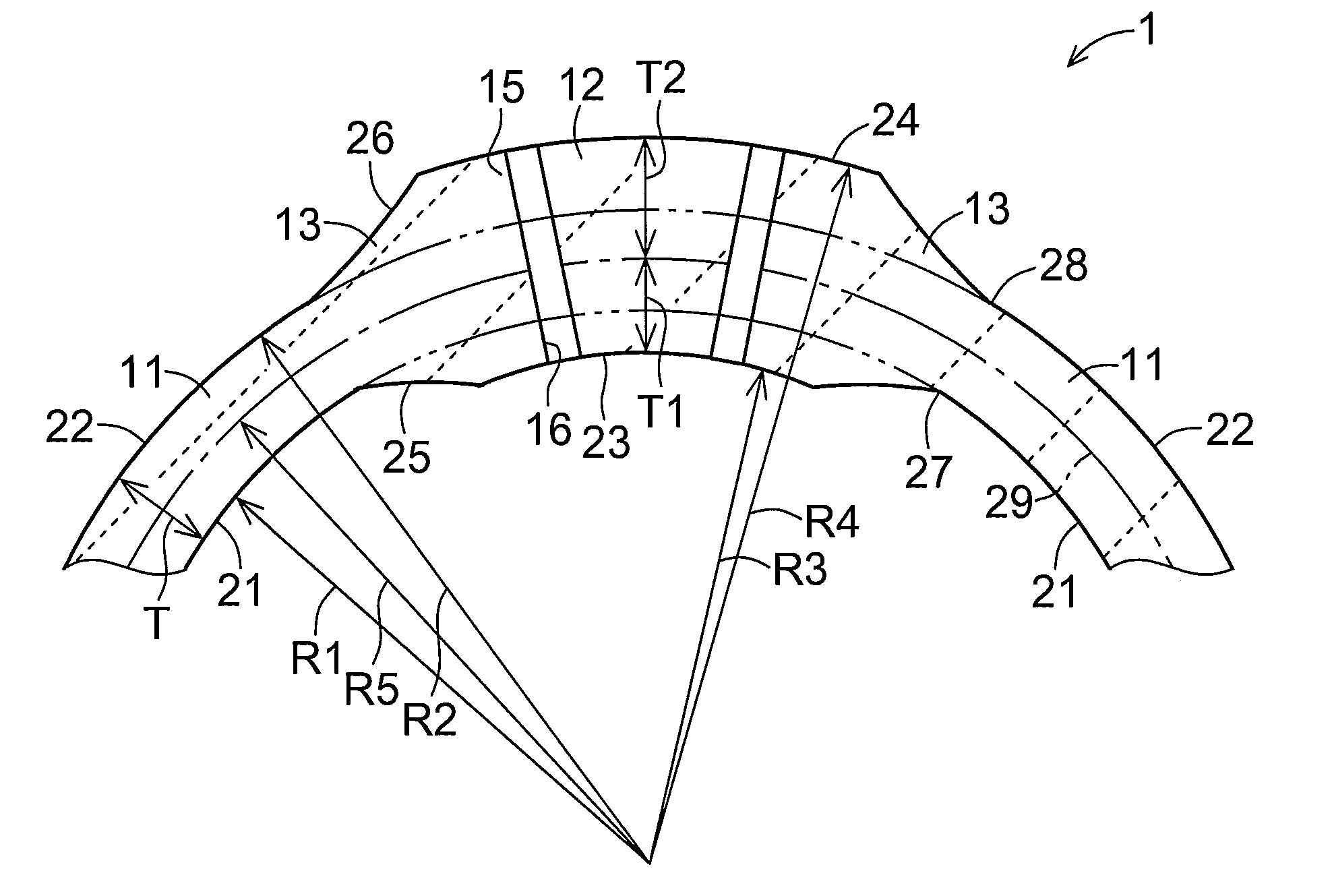
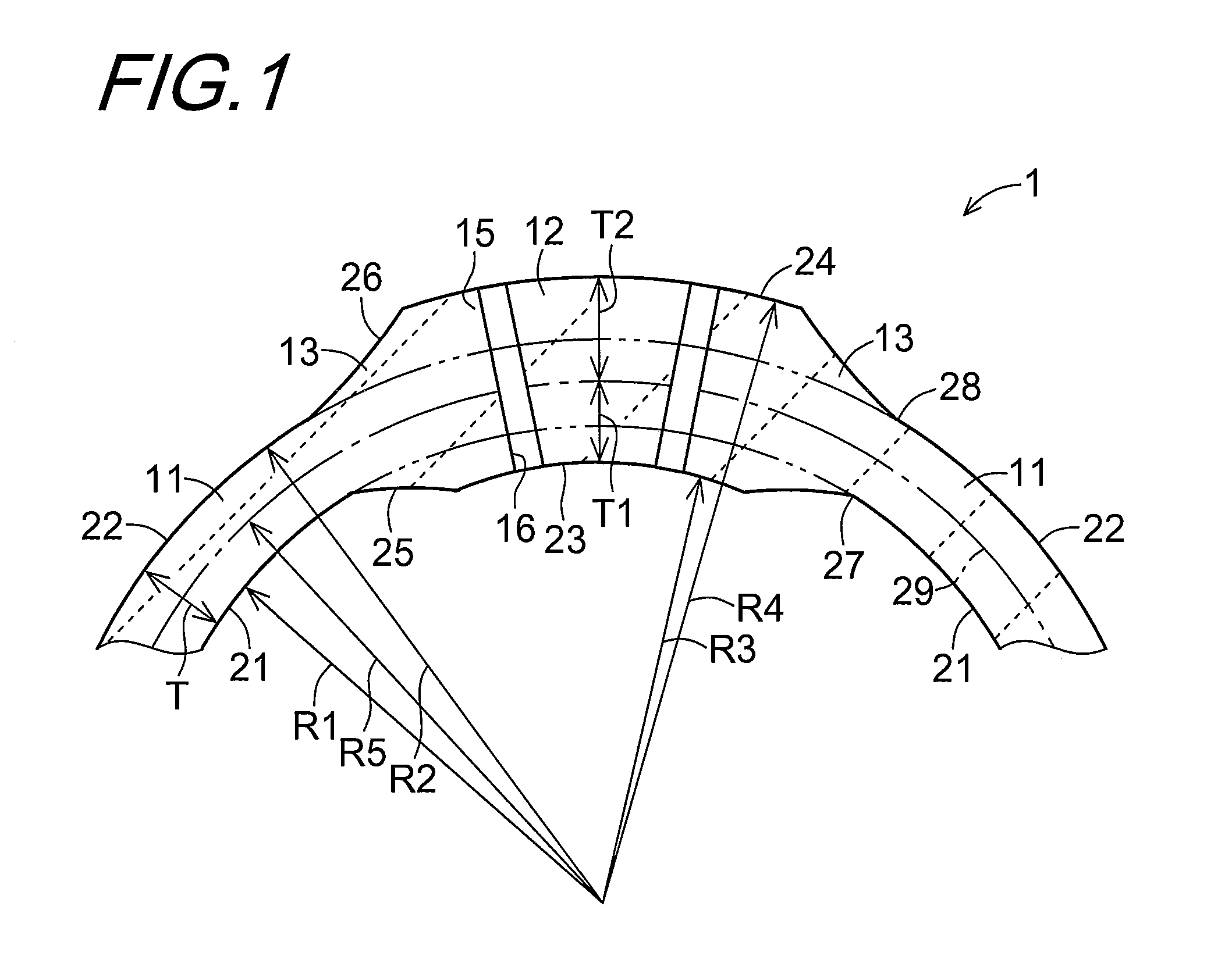
[0085]As a model, there was prepared a shell 1 having a through hole which has a diameter of 11.6 mm, in which the reference wall thickness T is 7.66 mm that is the thickness of the shell portion 11 and the values of the inner wall thickness T1 and the outer wall thickness T2 is 3.83 mm, respectively; that is, the thick-walled portion 12 was not formed. A pressure distribution analysis has been performed on the model by the finite element analysis under a pressure of 110 MPa equivalent to a pressure at a depth of 11000 m in the deep sea. In this construction, the first radius R1 was set at 210 mm. Moreover, the value of the minimum principal stress on that part of the 7.66 mm-thick shell portion 11 in spherical form which is located far enough away from the through hole 16 was found to be −1620 MPa.

TABLE 1Minimum principalMaximumstressprincipalReference wallInnerstressthicknessInner wallOuter wallDiameterAroundsurfaceAround(thickness ofthicknessthicknessof throughSeatingthroughbound...

example 2

[0087]Table 2 shows the result of a pressure distribution analysis, based on the finite element analysis, that has been performed on a model of the shell 1 having dimensions as shown in Table 2 under a pressure of 110 MPa equivalent to a pressure at a depth of 11000 m in the deep sea. The through hole 16 of Condition 2 and the through hole 16 of Condition 3 have different diameters, namely a diameter of 11.6 mm and a diameter of 12.8 mm, respectively. The ratio of stress for the area around the through hole 16 stands at 1.39 in Condition 2, yet stands at 1.43 in Condition 3. When the hole diameter was increased to 1.1 times, then the stress ratio was increased to 1.035 times. According to the result of the examination of Example 2 and the examination of Example 1 as well, the influence of variation of the hole diameter on the ratio of stress is not so significant.

TABLE 2Minimum principalMaximumstressprincipalReference wallInnerstressthicknessInner wallOuter wallDiameterAroundsurface...

example 3

[0088]Table 3 shows the result of a pressure distribution analysis, based on the finite element analysis, that has been performed on a model of the shell 1 having dimensions as shown in Table 2 under a pressure of 110 MPa equivalent to a pressure at a depth of 11000 m in the deep sea. The connecting portion 13 of Condition 4 and the connecting portion 13 of Condition 5 have different ranges, and more specifically the angle θ was set at 38° and the angle θ2 was set at 26° in Condition 4, and the angle θ1 was increased to 44° and the angle θ2 was set at 26° in Condition 5. The result showed that the increase of the connecting portion 13 range exerts little influence on the local maximum value of the minimum principal stress. The local maximum value of the maximum principal stress is decreased with an increase in the connecting portion 13 range, but, the local maximum value of the minimum principal stress is basically small. It is for this reason that there is little influence.

TABLE 3M...


PUM

PropertyMeasurementUnit
specific gravityaaaaaaaaaa
water depthaaaaaaaaaa
thicknessaaaaaaaaaa

Abstract

There are provided a shell of a pressure-resistant container that is made of ceramics, is used for a pressure-resistant container formed with a through hole, and can be made higher in strength and lighter in weight, as well as to provide a pressure-resistant container and an exploratory apparatus. A shell of a pressure-resistant container includes a shell portion and a thick-walled portion. The shell portion is made of ceramics and has a convexly-curved surface. The thick-walled portion is made of ceramics, continues into the shell portion, is larger in thickness than the shell portion, and has a through hole penetrating through the thick-walled portion in a thickness direction thereof.

Description

TECHNICAL FIELD[0001]The present invention relates to a shell of a pressure-resistant container for accommodating a measurement instrument such as a magnetometer for seabed exploration in deep-sea research activities, which exhibits high pressure-resistant capability under high-pressure conditions in the deep sea, as well as to a pressure-resistant container and an exploratory apparatus employing the same.BACKGROUND ART[0002]In pressure-resistant containers for use in deep-sea research activities, in response to strong demands for strength enhancement and weight reduction, a titanium alloy or the like has been used as the material of construction of a pressure-resistant structure for deep-sea use purposes. Such a related art is disclosed in Patent Literature 1.[0003]In this related art reference, there is described a titanium alloy-made pressure-resistant container composed of two head sections, each of which corresponds to a semispherical shell, and a barrel section having the shap...

Claims


Application Information

Patent Timeline
Patent Type & Authority Applications(United States)
IPC IPC(8): B65D6/00
CPCB63C11/48F17C2201/0123F16J12/00
Inventor ASAKAWA, KENICHIHYAKUDOME, TADAHIROYOSHIDA, MASAO
Owner JAPAN AGENCY FOR MARINE-EARTH SCIENCE AND TECHNOLOGY
Why Eureka
Try Eureka