High performance flow battery

a flow battery, high-performance technology, applied in the direction of indirect fuel cells, cell components, cell component details, etc., can solve the problems of limiting affecting the efficiency of flow batteries, and affecting the use of flow batteries, etc., to achieve the effect of high-performance flow batteries, charging, operating and using flow batteries

Inactive Publication Date: 2013-01-31
ZINC AIR
View PDF4 Cites 7 Cited by
  • Summary
  • Abstract
  • Description
  • Claims
  • Application Information

AI Technical Summary

Benefits of technology

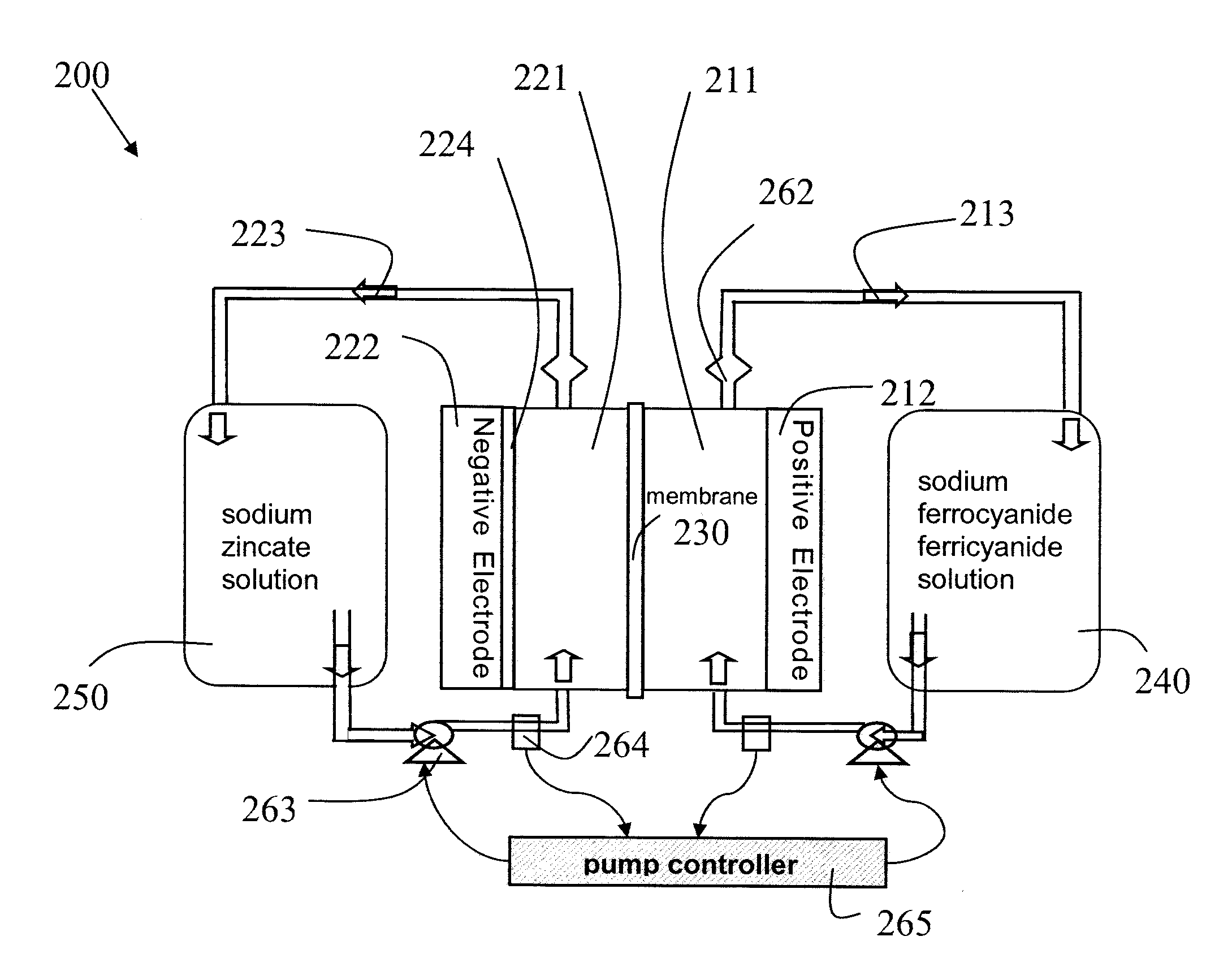
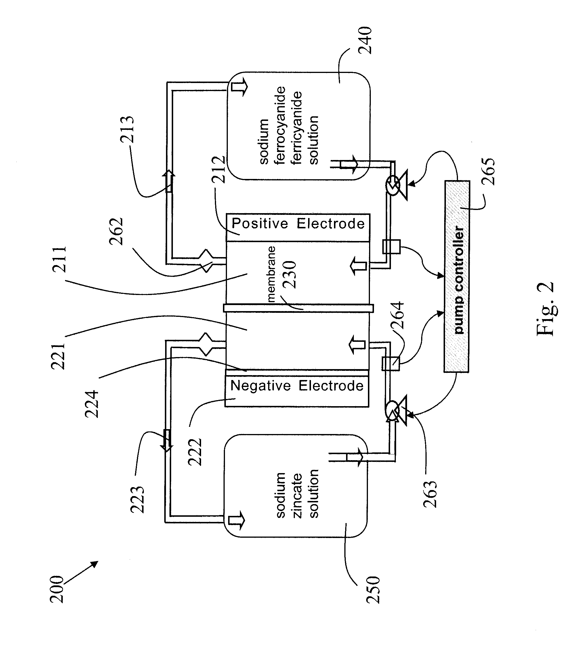
[0008]Second, a flow of electrolyte (for example, zinc species in the ZnFe battery) with a high level of mixing (also referred to herein as a “high rate of mixing” and “high mixing”) through at least one negative half cell in a Zn deposition region proximate a deposition surface where the electrolyte close to the deposition surface has sufficiently high zinc concentration for deposition rates on the deposition surface that sustain the uniform high current density. The electrolyte flow and mixing of the flow in the negative half cell are engineered to provide a mass transfer coefficient sufficient to support the high current density and to provide substantially uniform deposition of, for example zinc, over the deposition surface of a cell. Furthermore, some embodiments have been flow engineered to provide zinc deposition at less than a limiting current, where the deposited zinc has a dense, adherent, non-dendritic morphology.
[0010]Electrolyte flow with high mixing through the cell may be due to high fluid velocity in a parallel plate channel. However, the mixing in the flow may be induced by structures such as: conductive and non-conductive meshes; screens; ribbons; foam structures; arrays of cones, cylinders, or pyramids; and other arrangements of wires or tubes used solely or in combination with a planar electrode surface. Use of such structures may allow for high mixing of the electrolyte with laminar flow or with turbulent flow at high or low fluid velocity. Furthermore, structures for calming the turbulent flow may be included in the electrolyte fluid circuit immediately after the cell.

Problems solved by technology

The “greening” of the energy economy, increasing demand and use of renewable energy sources such as wind and solar, and the expected proliferation for example of plug-in hybrid vehicles and all electric vehicles, increasingly strain the electricity distribution grid.
High capacity electrical energy storage technologies such as pumped hydroelectric can play an important role in grid load balancing, time shifting renewable energy sources from time of generation to peak time of use, however, geography and cost limit their use, particularly on a local level.
Existing high capacity battery technologies, for example flow batteries, are too expensive for widespread adoption because the effective cost of the resulting energy and / or power delivered is well above market prices.

Method used


Image

  • High performance flow battery
  • High performance flow battery
  • High performance flow battery

Examples


Embodiment Construction

[0027]Embodiments of the present invention will now be described in detail with reference to the drawings, which are provided as illustrative examples of some embodiments of the invention so as to enable those skilled in the art to practice the invention. Notably, the figures and examples below are not meant to limit the scope of the present invention to a single embodiment, but other embodiments are possible by way of interchange of some or all of the described or illustrated elements. Moreover, where certain elements of the present invention can be partially or fully implemented using known components, only those portions of such known components that are necessary for an understanding of the present invention will be described, and detailed descriptions of other portions of such known components will be omitted so as not to obscure the invention. In the present specification, an embodiment showing a singular component should not be considered limiting; rather, the invention is in...


PUM

PropertyMeasurementUnit
operating current densityaaaaaaaaaa
Reynolds Numberaaaaaaaaaa
Sherwood Numberaaaaaaaaaa

Abstract

High performance flow batteries, based on alkaline zinc / ferro-ferricyanide rechargeable (“ZnFe”) and similar flow batteries, may include one or more of the following improvements. First, the battery design has a cell stack comprising a low resistance positive electrode in at least one positive half cell and a low resistance negative electrode in at least one negative half cell, where the positive electrode and negative electrode resistances are selected for uniform high current density across a region of the cell stack. Second, a flow of electrolyte, such as zinc species in the ZnFe battery, with a high level of mixing through at least one negative half cell in a Zn deposition region proximate a deposition surface where the electrolyte close to the deposition surface has sufficiently high zinc concentration for deposition rates on the deposition surface that sustain the uniform high current density. The mixing in the flow may be induced by structures such as: conductive and non-conductive meshes; screens; ribbons; foam structures; arrays of cones, cylinders, or pyramids; and other arrangements of wires or tubes used solely or in combination with a planar electrode surface. Third, the zinc electrolyte has a high concentration and in some embodiments has a concentration greater than the equilibrium saturation concentration—the zinc electrolyte is super-saturated with Zn ions.

Description

CROSS-REFERENCE TO RELATED APPLICATIONS[0001]This application claims the benefit of U.S. Provisional Applications Ser. Nos. 61 / 319,248 filed Mar. 30, 2010 and 61 / 322,780 filed Apr. 9, 2010, incorporated by reference in their entirety herein.FIELD OF THE INVENTION[0002]This invention relates to high performance electrochemical cells and batteries, and more particularly to flow batteries.BACKGROUND OF THE INVENTION[0003]The “greening” of the energy economy, increasing demand and use of renewable energy sources such as wind and solar, and the expected proliferation for example of plug-in hybrid vehicles and all electric vehicles, increasingly strain the electricity distribution grid. High capacity electrical energy storage technologies such as pumped hydroelectric can play an important role in grid load balancing, time shifting renewable energy sources from time of generation to peak time of use, however, geography and cost limit their use, particularly on a local level.[0004]Existing ...

Claims


Application Information

Patent Timeline
Patent Type & Authority Applications(United States)
IPC IPC(8): H01M2/38
CPCH01M2/38H01M8/20H01M8/188H01M8/04186H01M50/70Y02E60/10Y02E60/50
Inventor COOPER, JOHN F.WILKINS, HOWARD F.WITT, KEVINWILKINS, DAVIDWILSON, GREGORY J.HOLLANDSWORTH, ROGERGORDON, II, JOSEPH GROVERGOTCHER, ALAN J.SIKHA, GODFREY
Owner ZINC AIR
Why Eureka
Try Eureka