Ejection device and method of filling the ejection device with a material

a technology of ejection device and filling chamber, which is applied in the direction of teeth capping, instruments, packaged goods types, etc., to achieve the effect of increasing elastic reducing volume of the filling chamber, and easy formation

Active Publication Date: 2013-02-07
TOKUYAMA DENTAL CORP
View PDF13 Cites 13 Cited by
  • Summary
  • Abstract
  • Description
  • Claims
  • Application Information

AI Technical Summary

Benefits of technology

[0021]In the ejection device of the invention, the discharge portion is formed separately from the filling chamber and in a manner to be fitted to an opening on one end side of the filling chamber, the opening serving as a filling port for filling the material to be filled, and after the material to be filled is poured into the filling chamber through the filling port, the discharge portion is coupled to the filling chamber. Thus, the material to be filled is poured through the opening of the filling chamber, and no high pressure is applied to the material that is being poured into the filling chamber. Therefore, the material that is filled is prevented from separating into liquid components and solid components, or from being cured. Specifically, the conventional devices that are using a discharge portion having a nozzle of a small diameter are now liberated from the need of filling the material through the nozzle, which is a distinguished effect.
[0022]Further, the filling chamber is made of an elastic member so that the volume of the filling chamber elastically increases when the piston is pushed, a gap is formed between the main body and the filling chamber, and the volume of the filling chamber decreases when the piston is no longer pushed. Therefore, the material that is filled is prevented from adhering on the nozzle of the discharge portion.
[0023]Upon forming a groove or a step in the cylindrical container, further, the ejection device can be easily formed to meet the viscosity of the material that is filled. This is effective in releasing the air from the filling chamber or in preventing the leakage of the filled material particularly for the lowly viscous materials that are filled. Since no pressure is applied to the material that is filled, air bubbles are prevented from being mixed, too.

Problems solved by technology

In other words, if the material is poured from the rear end side of the body portion, the materials flows from the opening on the rear end side toward the filling surface on the front end side inevitably trapping the air on the way of flowing through the body portion and flowing into the filling surface.

Method used


Image

  • Ejection device and method of filling the ejection device with a material
  • Ejection device and method of filling the ejection device with a material
  • Ejection device and method of filling the ejection device with a material

Examples


first embodiment

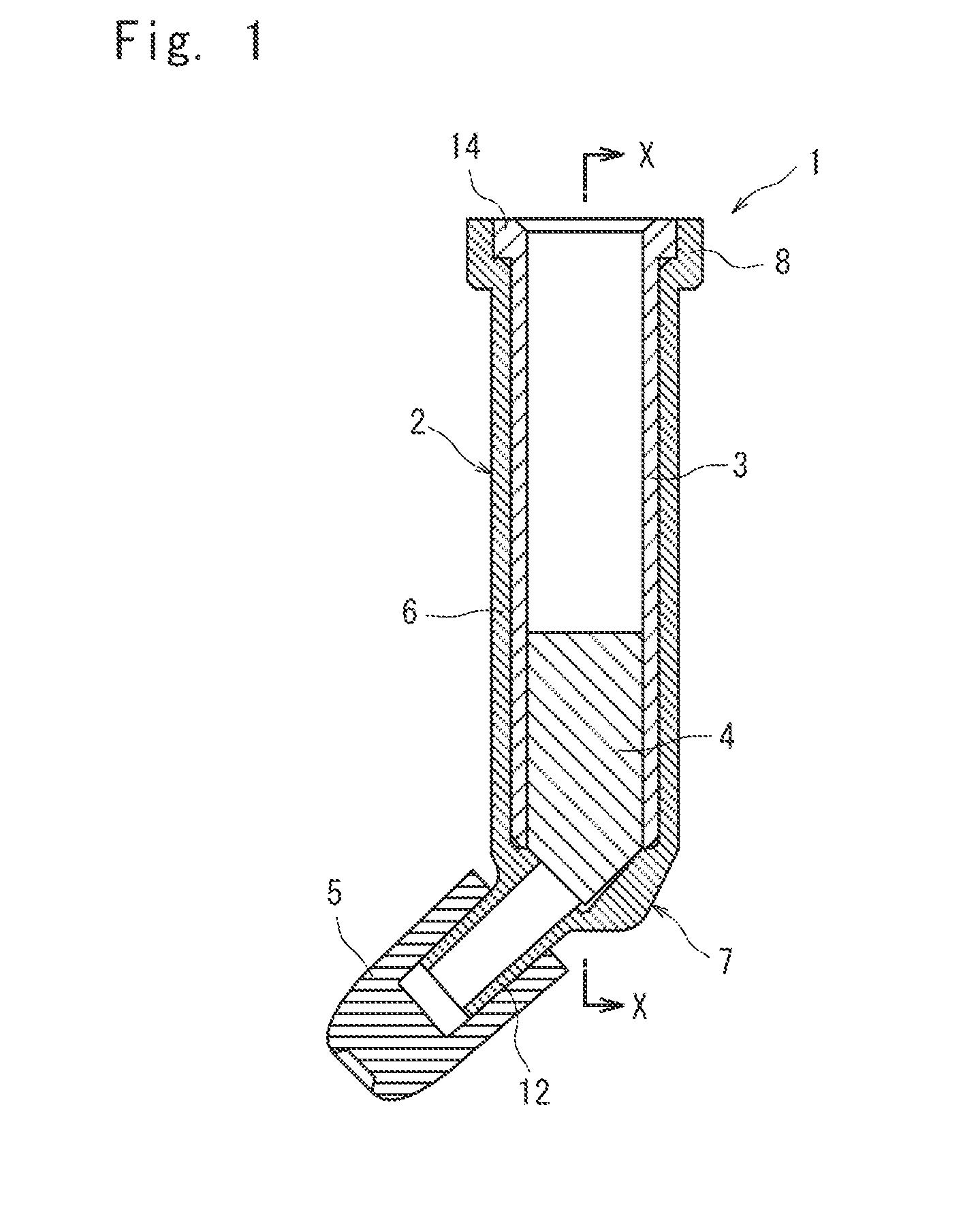
[0032]The ejection device according to the invention and a method of filling the ejection device with a material will now be described with reference to the drawings. In this specification, the side on where an end of the nozzle is present is referred to as the front end (front) side and the opposite side is referred to as the rear end (rear) side.

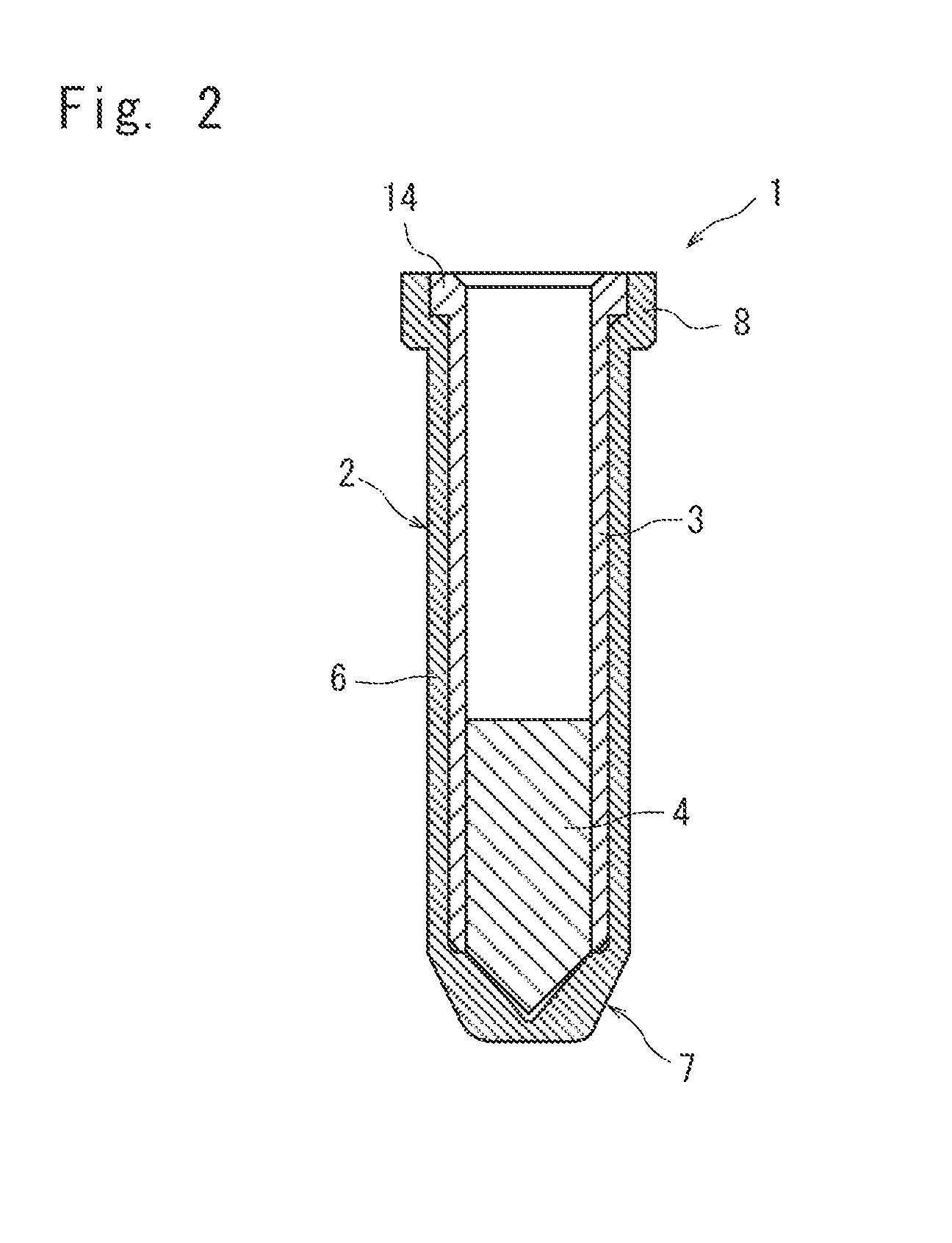
[0033]FIG. 1 is a sectional view of an ejection device for dental use according to the invention, FIG. 2 is a sectional view along the line X-X in FIG. 1, and FIG. 3 is a disassembled sectional view of the ejection device.

[0034]The ejection device 1 is, usually, discarded after it is used one time, and is constituted by a main body 2, a cylindrical member 3, a piston 4 and a cap 5, which are all made of a synthetic resin. The main body 2 is provided with a cylindrical body portion 6, and is forming a discharge portion 7 on the front end side of the body portion and a large diameter portion 8 on the rear end side integrally therewith. The b...

second embodiment

[0053]The ejection device according to the invention and a method of filling the ejection device with the material will be described next with reference to FIG. 6.

[0054]Referring to FIG. 6B, the ejection device 31 is constituted by a cylindrical member 32, a piston 33 and a discharge portion 34, which are all made of a synthetic resin.

[0055]In the above first embodiment, the main body 2 is provided, and the cylindrical member 3 is contained in the main body 2. In this embodiment, however, the main body 2 is omitted. In the above embodiment, further, the discharge portion 7 is formed integrally with the main body 2. In this embodiment, however, the discharge portion 34 is joined directly to the cylindrical member 32 making a difference from the above embodiment.

[0056]Referring to FIG. 6B, an annular groove 36 is formed in the inner periphery surface of an opening 35 at one end of the cylindrical member 32. Being corresponded to the annular groove 36, the discharge portion 34 forming ...

third embodiment

[0062]The ejection device according to the invention and a method of filling the ejection device with the material will be described next with reference to FIG. 7.

[0063]Referring to FIG. 7A, the ejection device 41 is constituted by a main body 42, a cylindrical member 43 and a piston 44, which are all made of a synthetic resin.

[0064]This embodiment is substantially different from the above first embodiment with respect to that a gap 46 is formed between the inner periphery surface of the main body 42 and the inner periphery surface of the cylindrical member 43 and that the cylindrical member 43 is made of a material that exhibits elasticity if the internal pressure exceeds a predetermined value.

[0065]In other words, a discharge portion 45 is formed integrally with the main body 42, and the cylindrical member 43 that forms the filling chamber 49 is separate from the main body 42 and the discharge portion 45. A stepped portion 47 is formed at the end of the cylindrical member 43 and a...


PUM

PropertyMeasurementUnit
diameteraaaaaaaaaa
inner diameteraaaaaaaaaa

Abstract

[Problems] To fill a container with a material without applying a high pressure to the material that is to be filled.[Means for Solution] An ejection device 1 comprises a filling chamber 24 formed in a cylindrical member for containing a material to be filled, a discharge portion 7 having a discharge nozzle 12 for pouring out the filled material to the exterior, and a piston 4 that pushes the filled material toward the front end side of the filling chamber 24 to discharge the filled material through the discharge nozzle 12. In the ejection device 1, the discharge portion 7 is formed separately from the filling chamber 24 and in a manner to be fitted to an opening on one end side of the cylindrical member 24, the opening serving as a filling port for filling the material to be filled, and after the material to be filled is poured into the filling chamber 24 through the filling port, the discharge portion 7 is coupled to the filling chamber 24.

Description

TECHNICAL FIELD[0001]This invention relates to an ejection device which enables a container to be filled with a viscous material or enables a container having a nozzle of a small diameter to be filled with a viscous material without applying a high pressure, and to a method of filling the ejection device with the material.BACKGROUND ART[0002]A patent document 1 described below is disclosing a disposable container filled with a material for dental treatment. On other words, the disposable container is filled with the material for dental treatment in an amount sufficient for the use of one time and is, usually, discarded after the use of one time. The container is provided with a cylindrical body portion, and has a nozzle formed at a front end of the body portion and a piston contained in the body portion. Before the material is being filled, the piston is disposed on the front end side of the body portion, i.e., is disposed on the nozzle side.[0003]To pour the material into the dispo...

Claims


Application Information

Patent Timeline
Patent Type & Authority Applications(United States)
IPC IPC(8): B65B3/12B65D83/76
CPCA61C5/062A61C5/62A61C5/66B05C17/00579
Inventor YAMAGUCHI, NOBUTOSHIAKIZUMI, HIRONOBUANDOH, YUSAKU
Owner TOKUYAMA DENTAL CORP
Why Eureka
Try Eureka