Power Conversion Device

a power conversion device and power technology, applied in the direction of electric generator control, dynamo-electric converter control, dynamo-electric gear control, etc., can solve the problems of increasing power loss and heat generation, and achieve the effect of reducing switching losses and suppressing current waveform turbulen

Inactive Publication Date: 2013-02-07
HITACHI LTD
View PDF2 Cites 33 Cited by
  • Summary
  • Abstract
  • Description
  • Claims
  • Application Information

AI Technical Summary

Benefits of technology

[0015]According to the present invention, in a power conversion device, it is possible to suppress turbulence of the current waveform, and also to reduce switching losses.
[0016]It should be understood that, in the embodiment described below, solutions are found as seems desirable for various problems relating to manufacture as a commercial product, as will be described hereinafter.

Problems solved by technology

However, when the switching elements described above change over from the interrupted state to the continuous state, or when they change over from the continuous state to the interrupted state, the power loss increases, and the amount of heat generated also increases.

Method used


Image

  • Power Conversion Device
  • Power Conversion Device
  • Power Conversion Device

Examples


Embodiment Construction

[0056]In addition to the details described in the foregoing sections TECHNICAL PROBLEM and ADVANTAGEOUS EFFECT OF THE INVENTION, in the following embodiment, it is possible to solve problems that need to be solved from the point of view of improvement of productivity, and, furthermore, advantageous effects are obtained from the point of view of productivity. Along with the following explanation of an embodiment, concrete solutions for such problems and concrete advantages will be explained.

[0057][Reduction of the Switching Frequency of the Switching Elements]

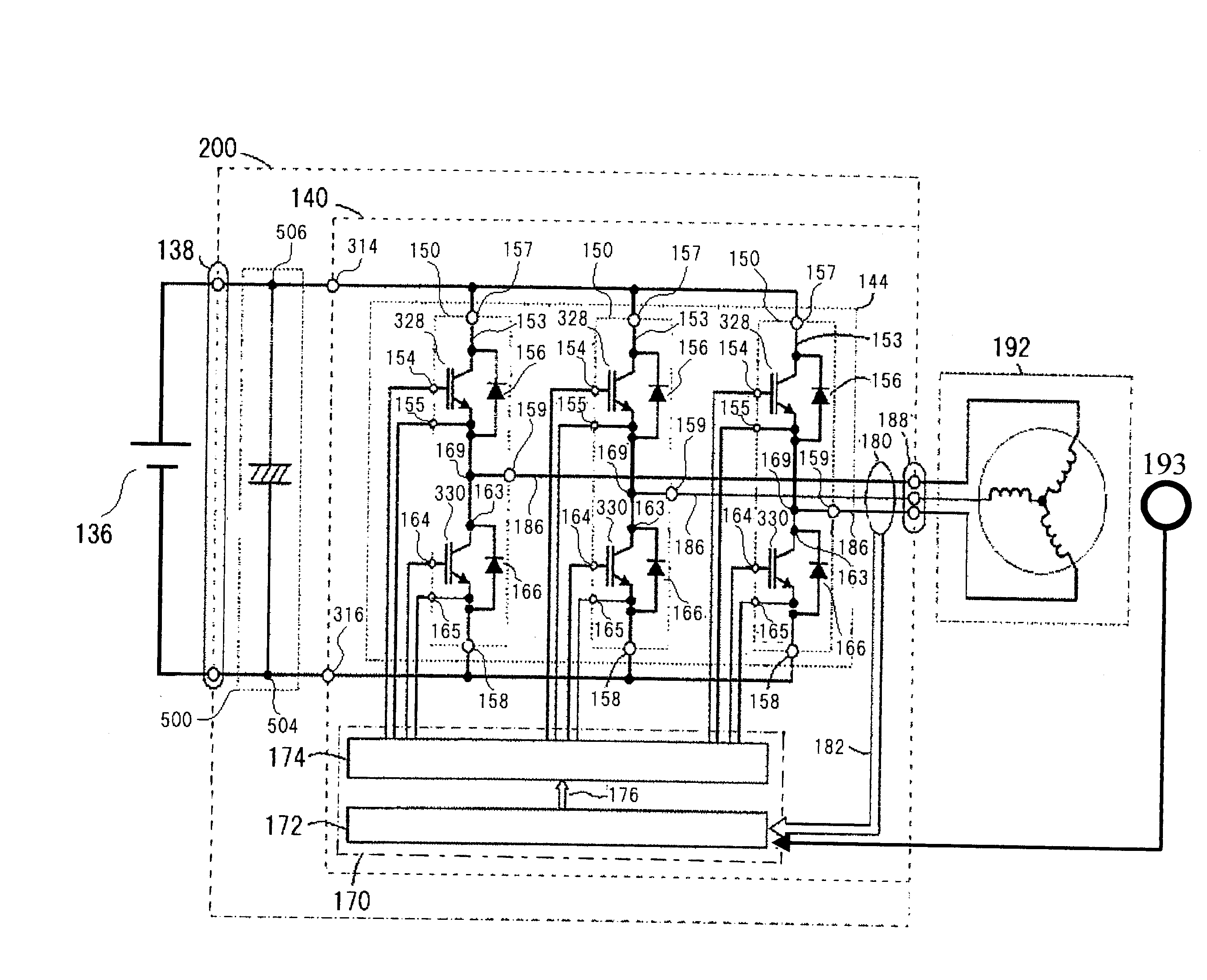
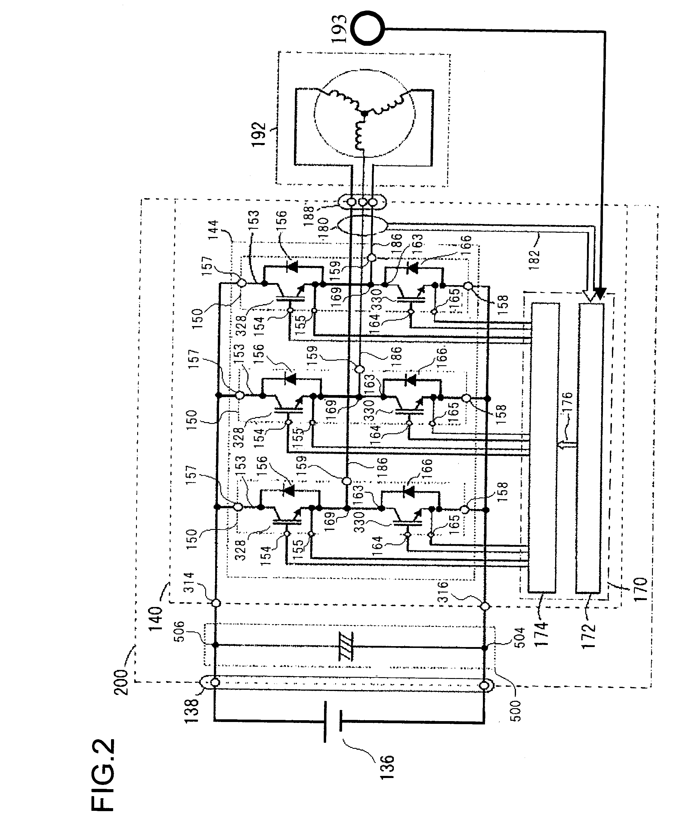
[0058]Since, with the power conversion device explained in the embodiment below, the switching operation of the switching elements is controlled on the basis of an AC output that is converted from DC power, for example on the basis of its waveform angle, in other words on the basis of its phase, accordingly drive signals are supplied from a drive circuit to the switching elements described above, and the switching elements perfo...


PUM


Abstract

A control circuit of a power conversion device calculates voltage command signals for determining timings for making switching elements of a power switching circuit continuous by performing feed forward control on the basis of input information, and feedback control on the basis of the input information and current values of AC output, for each of the d axis and the q axis of a motor.

Description

TECHNICAL FIELD[0001]The present invention relates to a power conversion device that converts DC power into AC power, or AC power into DC power.BACKGROUND ART[0002]A power conversion device that receives DC power and that converts this DC power into AC power for supply to a rotating electrical machine includes a plurality of switching elements, and converts the DC power that is supplied into AC power by these switching elements repeating their switching operation. Many power conversion devices such as described above can also be used for converting AC power induced in a rotating electrical machine to DC power by switching operation of the switching elements described above. Generally, the switching elements described above are controlled on the basis of a pulse width modulation method (hereinafter termed the “PWM method”), employing a carrier wave that changes at a constant frequency. The control accuracy can be enhanced by increasing the frequency of the carrier wave, and there is ...

Claims


Application Information

Patent Timeline
Patent Type & Authority Applications(United States)
IPC IPC(8): H02P21/00H02M7/537
CPCH02M7/53875H02M2001/0016H02M2007/53876H02P2209/09Y02B70/1491H02M2001/0054H02P21/0003Y02B70/10H02M1/0016H02M1/0054H02M7/53876
Inventor FURUKAWA, KIMIHISAMITSUI, TOSHISADANISHIGUCHI, SHINGOOOYAMA, KAZUTOMIYAZAKI, HIDEKIKAMIYA, AKINORI
Owner HITACHI LTD
Why Eureka
Try Eureka