Carrier-envelope-phase stabilization of a master oscillator optical amplifier system

a master oscillator and optical amplifier technology, applied in the direction of laser details, instruments, electrical apparatus, etc., can solve the problems of total cep instability, non-integration of approaches, and unstable cep of amplified pulses

Active Publication Date: 2013-02-07
COHERENT INC
View PDF0 Cites 10 Cited by
  • Summary
  • Abstract
  • Description
  • Claims
  • Application Information

AI Technical Summary

Benefits of technology

[0009]In one aspect of an apparatus in accordance with the present invention comprises an oscillator arrangement including a laser cavity for generating modelocked optical pulses from which a sequence thereof, having a predetermined pulse-repetition frequency (PRF), is selected for amplification. An optical amplifier arrangement is provided for amplifying the sequence of optical pulses selected for amplification and delivering a corresponding sequence of amplified pulses. An arrangement for periodically generating, at a maximum frequency less than or equal to the PRF of the sequence of optical pulses, a first signal representative of the instant carrier-envelope phase (CEP) of the pulses in the sequence of amplified pulses. Electronic means are provided for dividing the first signal into second and third signals. The second signal includes frequency components in a first range between DC and a first frequency less than the maximum frequency, and the third signal includes frequency components in a second range between a second frequency less than the maximum frequency and the maximum frequency. A slow-response CEP-controller and a fast-response CEP-controller are provided for adjusting the CEP of the pulses in the sequence of amplified pulses. Each of the CEP-controllers is located outside of the laser cavity of the oscillator arrangement. A first signal processing device is arranged to receive the second signal, and a second signal processing device is arranged to receive the third signal. The first and second signal processing devices are arranged to generate respectively first and second control signals, each thereof representative of a difference between the instant and a desired CEP of the pulses in the sequence of amplified pulses. The first and second control signals adjust respectively the slow-response and fast-response CEP-controllers to minimize the difference between the instant and the desired CEP of the pulses in the sequence of amplified pulses.

Problems solved by technology

It has been found, however, that if a pulse from a CEP-stabilized oscillator is amplified in a chirped pulse amplification arrangement the CEP of the amplified pulses will usually not be stable.
A problem with this and other prior-art approaches to CEP control in a master-oscillator-plus-amplifier system is that the approaches do not take into account that different factors contribute to total CEP instability.
Moving this element during operation could interfere with the mode-locking of the oscillator.
A further shortcoming of the disclosure of the Yu et al. patent is that it does not address the problem of controlling the CEP of an oscillator-plus-amplifier system.

Method used


Image

  • Carrier-envelope-phase stabilization of a master oscillator optical amplifier system
  • Carrier-envelope-phase stabilization of a master oscillator optical amplifier system
  • Carrier-envelope-phase stabilization of a master oscillator optical amplifier system

Examples


Embodiment Construction

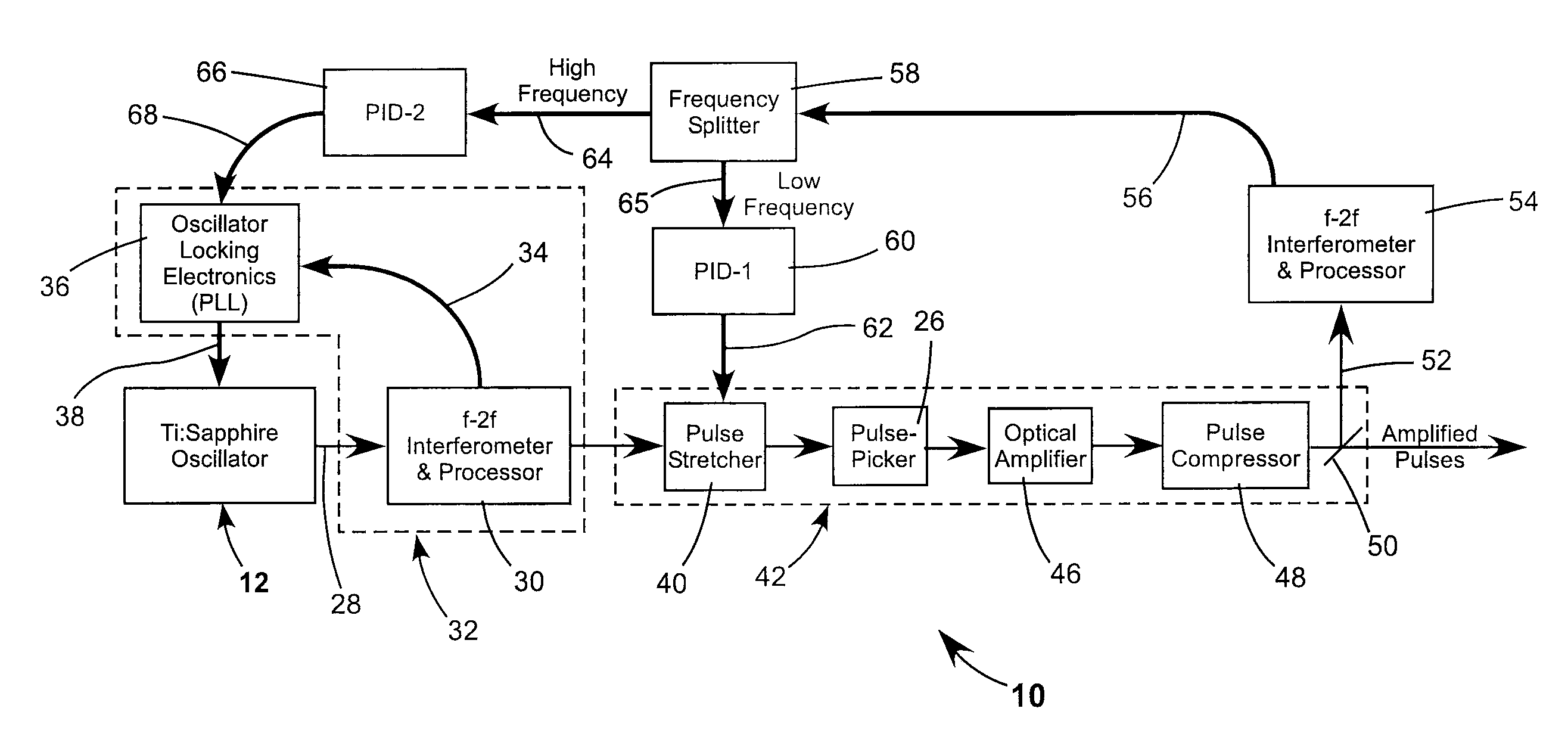
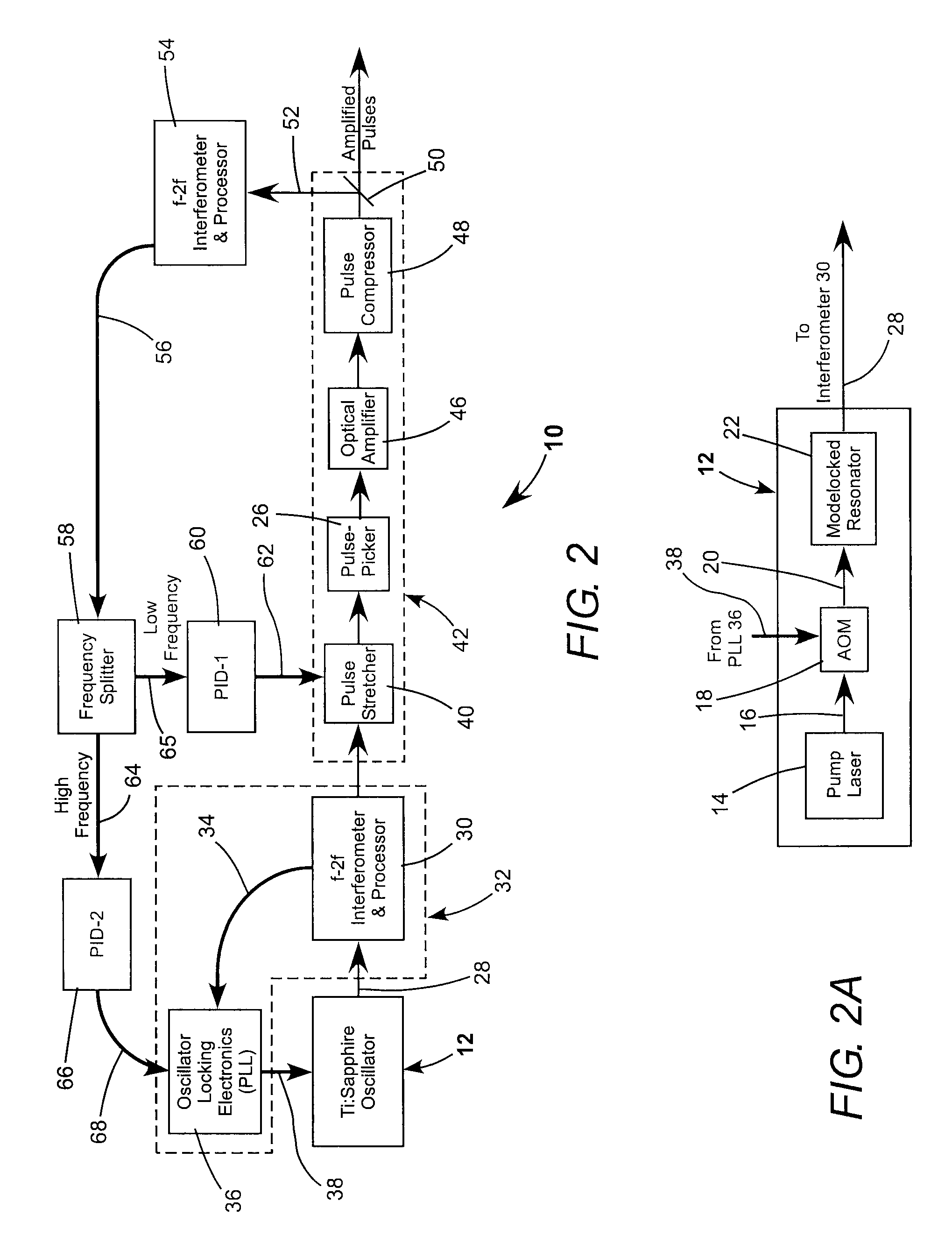
[0019]Continuing with reference to the drawings wherein like features are designated by like reference numerals, FIG. 2 and FIG. 2A schematically illustrate one preferred embodiment 10 of ultrafast oscillator-amplifier apparatus in accordance with the present invention. In these drawings, and in other drawings referred to further herein below, electrical paths are depicted by bold lines and optical paths are depicted by fine lines.

[0020]Apparatus 10 includes an ultrafast laser oscillator 12, here, an oscillator including a titanium-doped sapphire (Ti:sapphire) gain-medium. Oscillator 12 (see FIG. 2A) includes a pump-laser 14 which delivers a beam 16 of pump-radiation. A modulator 18, such as an AOM, is provided for selectively modulating beam 16 to provide a modulated pump-beam 20. Beam 20 optically pumps a Ti:sapphire gain medium (not shown) in a modelocked laser-resonator (laser-cavity) 22. Resonator 22 delivers a sequence 28 of modelocked pulses at a pulse-repetition frequency on...


PUM


Abstract

A laser and amplifier combination delivers a sequence of optical pulses at a predetermined pulse-repetition frequency PRF. An interferometer generates a signal representative of the carrier-envelope phase (CEP) of the pulses at intervals corresponding to the PRF. The signal includes frequency components from DC to the PRF. The signal is divided into high and low frequency ranges. The high and low frequency ranges are sent to independent high frequency and low frequency control electronics, which drive respectively a high-frequency CEP controller and a low frequency controller for stabilizing the CEP of pulses in the sequence.

Description

TECHNICAL FIELD OF THE INVENTION[0001]The present invention relates in general to laser oscillator-plus-amplifier arrangements for delivering femtosecond pulses. The invention relates in particular to such arrangements wherein a laser pulse is temporally stretched prior to amplification and the amplified pulse is temporally compressed before delivery.DISCUSSION OF BACKGROUND ART[0002]Optical pulses having a duration of a few femtoseconds or less may include only a few optical cycles at a fundamental carrier frequency of the pulse within an envelope of the pulse. A pulse-envelope typically has a Gaussian or Sech-squared form. The peak power within the envelope will depend on the phase of the carrier cycles relative to the envelope. This is referred to by practitioners of the art as the carrier envelope phase (CEP). FIG. 1A is a graph schematically illustrating a condition where the carrier is retarded in phase by an amount φCE with respect to the pulse envelope. The highest peak powe...

Claims


Application Information

Patent Timeline
Patent Type & Authority Applications(United States)
IPC IPC(8): H01S3/098
CPCH01S3/1305H01S3/1307H01S3/2308H01S3/0057H01S3/136H01S3/0085G01J11/00H01S3/1106H01S3/1301H01S3/1312
Inventor SCHILL, ALEXANDER W.LI, CHENGQUANFERU, PHILIPPE
Owner COHERENT INC
Why Eureka
Try Eureka