Radiation generating apparatus and radiation imaging apparatus

a radiation generation apparatus and radiation imaging technology, applied in the direction of x-ray tubes, material analysis using wave/particle radiation, instruments, etc., can solve the problems of reducing the radiation quantity increasing the size of the envelope, so as to reduce the radiation quantity, reduce the size of the entire apparatus, and secure the effect of voltage characteristics

Active Publication Date: 2013-02-07
CANON KK
View PDF3 Cites 23 Cited by
  • Summary
  • Abstract
  • Description
  • Claims
  • Application Information

AI Technical Summary

Benefits of technology

[0011]The present invention can both downsize the entire apparatus and secure withstanding voltage characteristics in a balanced manner. The downsizing allows

Problems solved by technology

Also, there is a problem in that if the X-ray tube is damaged by electrical discharges, X-rays cannot be generated stably for a long period of time.
However, withstanding voltage performance of insulating liquids such as insulating coolant oil is more susceptible to electrode shape, electrode surface properties, temperature, impurities, convection, and the like than other insulating materials.
Consequently, the envelope grows in size, increasing the size and weight of the entire X-ray generating apparat

Method used


Image

  • Radiation generating apparatus and radiation imaging apparatus
  • Radiation generating apparatus and radiation imaging apparatus
  • Radiation generating apparatus and radiation imaging apparatus

Examples


first embodiment

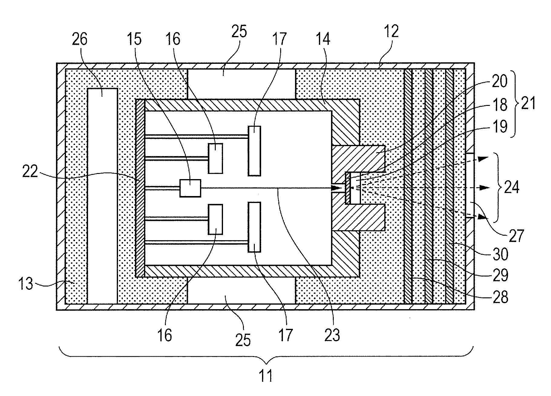
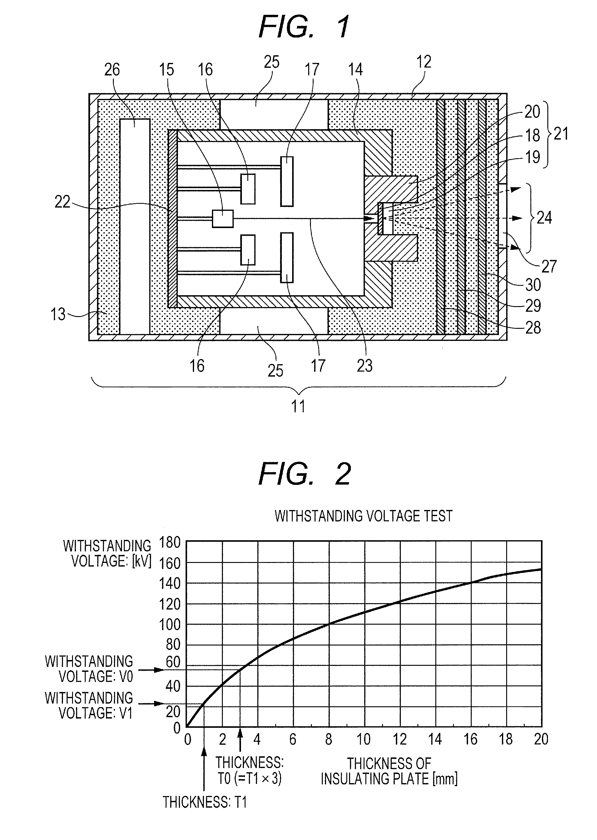
[0023]FIG. 1 is a schematic sectional view of a radiation generating apparatus (transmission type radiation source) 11 according to the present embodiment.

[0024]A transmission type radiation tube 14 is housed in an envelope 12, with an insulating fluid 13 filling between the envelope 12 and radiation tube 14. The radiation tube 14 is tubular in shape and is held in the envelope 12 when a body of the radiation tube 14 is connected to a holding member 25 fixed to an inner wall of the envelope 12. The insulating fluid 13 is designed to be able to circulate around the radiation tube 14. Examples of materials available for the envelope 12 include metals such as iron, stainless steel, lead, brass and copper. As a fill port (not shown) for the insulating fluid 13 is provided in part of the envelope 12, the insulating fluid 13 can be poured into the envelope 12 through the fill port. A pressure relief port (not shown) made of elastic material is installed, as required, in part of the envelo...

second embodiment

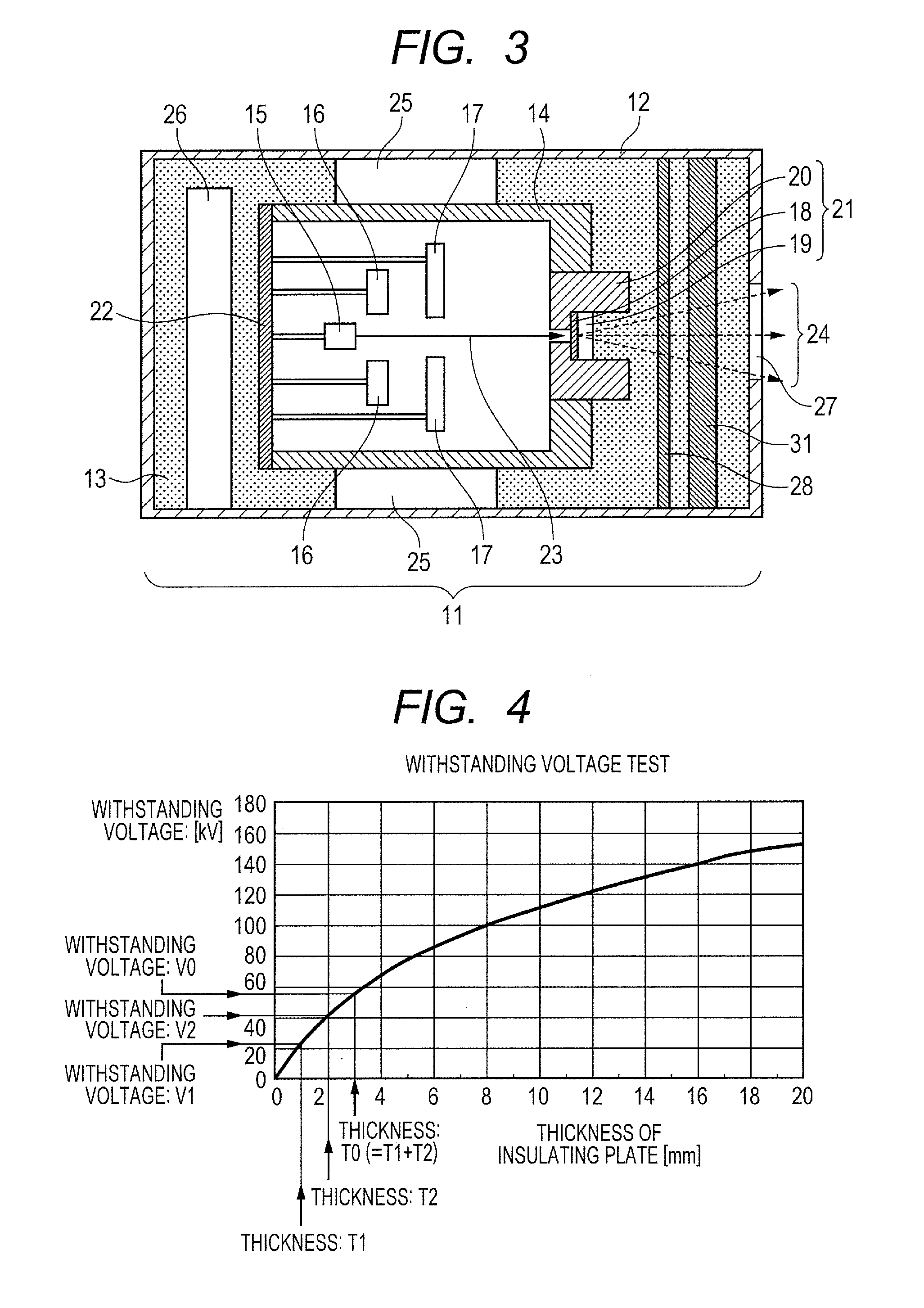
[0048]FIG. 3 is a schematic sectional view of a radiation generating apparatus 11 according to the present embodiment.

[0049]The radiation generating apparatus (transmission type radiation source) 11 according to the present embodiment differs from the first embodiment in that two plates 28 and 31 of different thicknesses are placed between the first window 27 and second window 19. Otherwise, the present embodiment is the same as the first embodiment, and thus description of components other than the plates 28 and 31 as well as configuration of the radiation generating apparatus 11 will be omitted.

[0050]According to the present embodiment, two plates and 31 are arranged side by side between the first window 27 including its periphery and the second window 19 including its periphery by being separated by a gap. The gap is also filled with the insulating fluid 13 which fills between the inner wall of the envelope 12 and the radiation tube 14. Consequently, the radiation 24 is emitted o...

third embodiment

[0058]FIG. 5 is a schematic sectional view of a radiation generating apparatus 11 according to the present embodiment.

[0059]As shown in FIG. 5, the radiation generating apparatus (transmission type radiation source) 11 according to the present embodiment differs from the first embodiment in that a gas is used as the insulating fluid 13. Otherwise, the present embodiment is the same as the first embodiment, and thus description of components other than the insulating fluid 13 as well as configuration of the radiation generating apparatus 11 will be omitted.

[0060]Gaseous insulating fluids 13 available for use include sulfur hexafluoride which has insulation performance equivalent to that of mineral oil-based insulating oil.

[0061]In this way, by adopting the configuration described above, the present embodiment provides advantages similar to those of the first embodiment. Furthermore, since a gas is used as the insulating fluid 13, the weight of apparatus can be made lighter than when ...


PUM


Abstract

The present invention relates to a radiation generating apparatus which includes an envelope provided with a first window through which radiation is transmitted, a radiation tube housed in the envelope and provided with a second window through which the radiation is transmitted, the second window being located at a position opposite the first window, and an insulating fluid adapted to fill between the inner wall of the envelope and the radiation tube. Plural plates are arranged side by side between the first window including its periphery and the second window including its periphery by overlapping one another via gaps. The gaps is formed among the plates, thereby the withstanding voltage between the first window and second window is made larger.

Description

BACKGROUND OF THE INVENTION[0001]1. Field of the Invention[0002]The present invention relates to a radiation generating apparatus equipped with a radiation tube in an envelope filled with an insulating fluid as well as to a radiation imaging apparatus which uses the radiation generating apparatus.[0003]2. Description of the Related Art[0004]A radiation generating apparatus is known which includes a radiation tube housed in an envelope, where the radiation tube in turn includes an electron source and target placed in an enclosed internal space. The radiation generating apparatus generates radiation by irradiating the target with electrons emitted from the electron source.[0005]To generate radiation suitable for radiography, it is necessary to apply a voltage as high as 40 kV to 150 kV between the electron source and target, the electron source being a cathode in the radiation tube, and irradiate the target with an electron beam accelerated to high energies. Generally, the envelope is...

Claims


Application Information

Patent Timeline
IPC IPC(8): H01J35/18H01J35/20G01N23/04
CPCH01J35/04H01J35/16H01J35/18H01J2235/06H01J2235/087H01J2235/1204H01J2235/186H01J2235/122H01J2235/1262H01J2235/1291H01J2235/16H01J2235/167H01J2235/1216H01J35/116H01J35/186
Inventor AOKI, SHUJIYAMAZAKI, KOJIYANAGISAWA, YOSHIHIROUEDA, KAZUYUKITAMURA, MIKI
Owner CANON KK
Why Eureka
Try Eureka