
Method and system for operating electron guns in magnetic fields

a technology of electron guns and magnetic fields, applied in the field of electron guns, can solve the problems of limiting the use of medical linacs to gating or dynamic multi-leaf collimators (dmlc), or a combination of these two radiation treatment modalities

Inactive Publication Date: 2013-02-07
THE BOARD OF TRUSTEES OF THE LELAND STANFORD JUNIOR UNIV
View PDF3 Cites 6 Cited by
  • Summary
  • Abstract
  • Description
  • Claims
  • Application Information

AI Technical Summary

Benefits of technology

The patent describes a method for configuring an electron gun for injecting an electron beam into an MRI scanner's magnetic fringe fields without using a magnetic shield. A computer program is used to determine the appropriate diameters of the anode drift tube and Type M cathode based on the magnetic field and current density. The transverse diameter of the cathode is also determined based on the anode drift tube diameter and current density. The emittance of the electron beam is then minimized by optimizing the distance between the cathode and the anode, ensuring that the electron beam is directed close to the axis of symmetry of the MRI magnetic field. This method allows for optimal electron beam injection and improved MRI image quality.

Problems solved by technology

This fact limits the use of the medical linac to gating or dynamic multileaf collimator (DMLC), or a combination of these two radiation treatment modalities.

Method used


Image

  • Method and system for operating electron guns in magnetic fields
  • Method and system for operating electron guns in magnetic fields
  • Method and system for operating electron guns in magnetic fields

Examples


Embodiment Construction

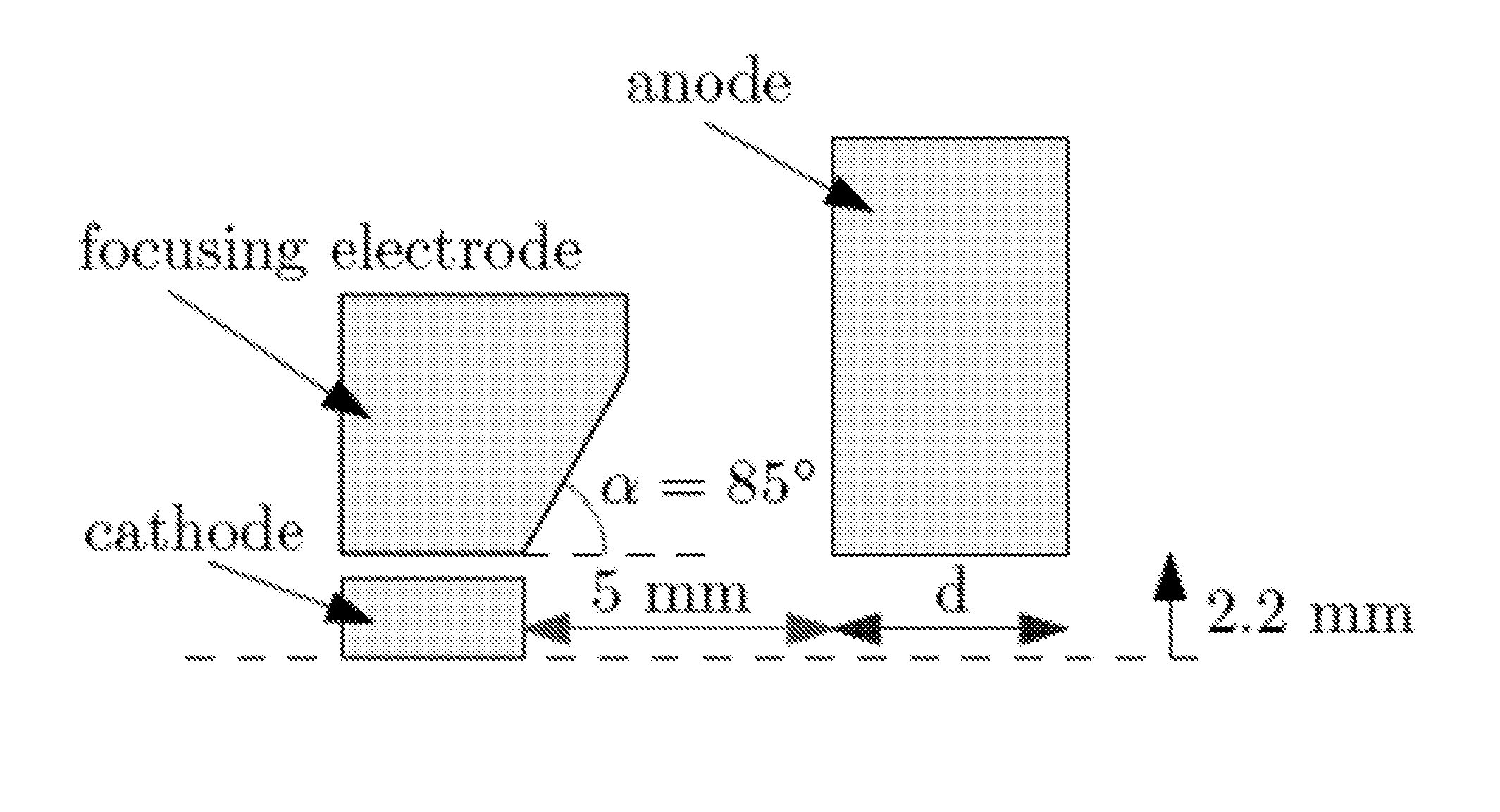
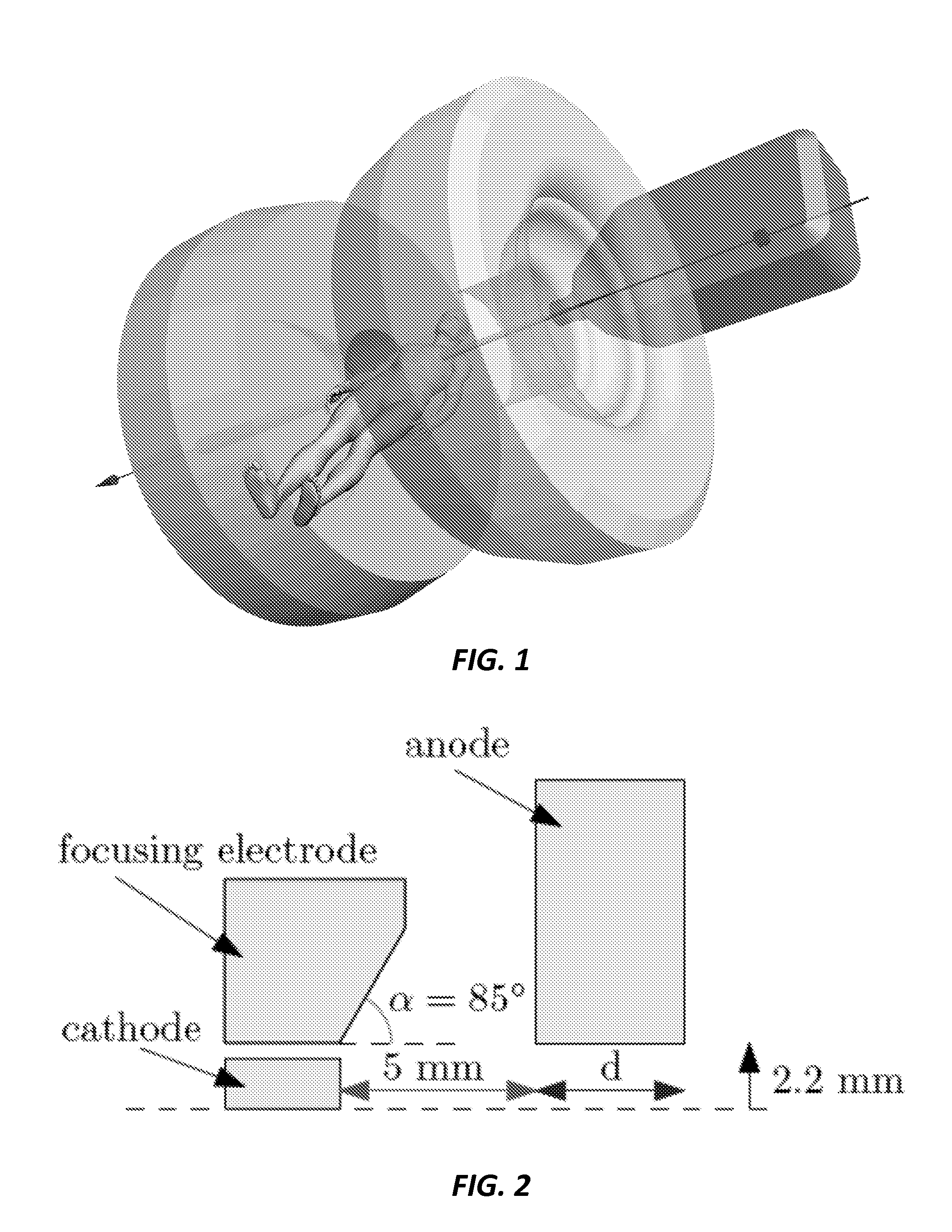
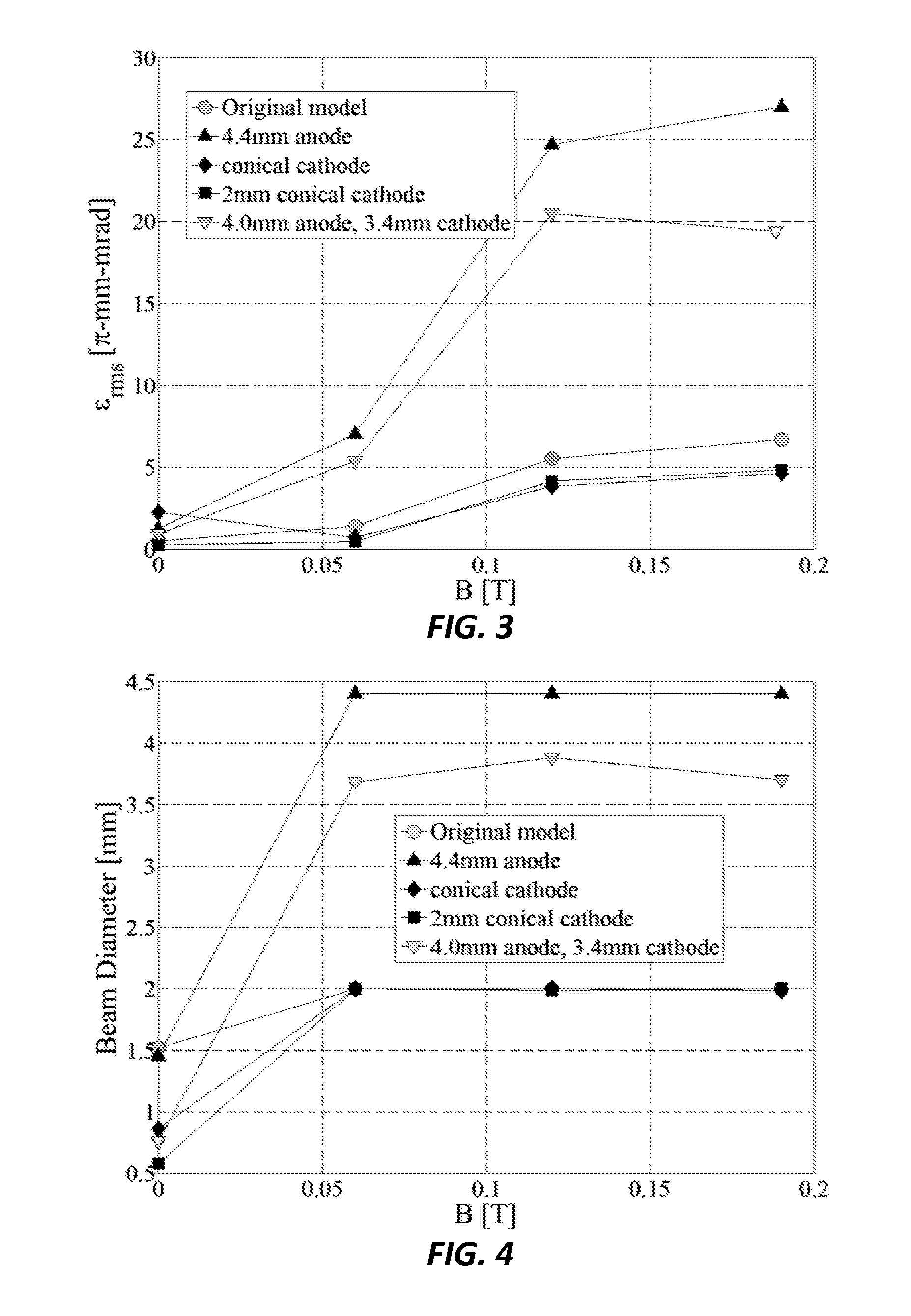
[0020]In the following description, a specially designed electron gun is provided, which can operate in the presence of strong magnetic fringe fields of MRI magnets. Computer simulations show that the electron gun can produce high quality beams, which can be injected into a straight through medical linac waveguide like the Varian 600 C linac with more efficiency in the presence of axisymmetric external magnetic fields.

[0021]The current invention provides an electron gun configuration, which enables a new MRI-linac configuration capable of making full use of the positional information provided by the MRI scanner and adapts the linac orientation so it can track the tumor motion and continuously deliver dose. This electron gun and MRI-linac configuration, called robotic linac adaptation (RLA) configuration, is a generalization of the in-line MRI-linac configuration with no magnetic shielding.

[0022]The RLA configuration is based on the observation that an electron beam will stay confine...


PUM


Abstract

A method of configuring an electron gun for generating and injecting an electron beam into a linac accelerating waveguide operating in magnetic fringe fields of an MRI scanner in the absence of a magnetic shield is provided using an appropriately programmed computer to determining an anode drift tube diameter at an injection point of a linac according to a magnetic field value from an MRI scanner and to a predetermined current density, where the magnetic field has an isocenter, determining a transverse diameter of a Type M cathode in an electron gun, according to the anode drift tube diameter and the current density, and minimizing an emittance value in an electron beam of the electron gun at an entry point of the anode drift tube by optimizing the distance between the cathode and the anode, where the electron beam is along an axis of symmetry of the magnetic field.

Description

CROSS-REFERENCE TO RELATED APPLICATIONS[0001]This application is a continuation-in-part of U.S. patent application Ser. No. 13 / 565343, filed Aug. 2, 2012, which is incorporated herein by reference. U.S. patent application Ser. No. 13 / 565343, filed Aug. 2, 2012 claims the benefit of U.S. Provisional Patent Application 61 / 626009 filed Sep. 19, 2011, which is incorporated herein by reference. Application Ser. No. 13 / 565343 filed Aug. 2, 2012 claims priority from U.S. Provisional Patent Application 61 / 574432, which is incorporated herein by reference.STATEMENT OF GOVERNMENT SPONSORED SUPPORT[0002]This invention was made with Government support under contract T32-CA09695 awarded by National Institutes of Health (NIH). The Government has certain rights in this invention.FIELD OF THE INVENTION[0003]The invention relates generally to electron guns. More particularly, the invention relates to electron gun geometry capable to robustly function in the presence of high strength external magneti...

Claims


Application Information

Patent Timeline
Patent Type & Authority Applications(United States)
IPC IPC(8): G06F17/50
CPCH01J3/027H05H2007/084H05H7/08H01J3/029
Inventor CONSTANTIN, DRAGOS E.FAHRIG, REBECCAKEALL, PAUL J.
Owner THE BOARD OF TRUSTEES OF THE LELAND STANFORD JUNIOR UNIV
Learn More