Imaging apparatus and driving method of the imaging apparatus

a driving method and imaging apparatus technology, applied in the direction of television systems, radioation controlled devices, instruments, etc., can solve the problems of long time for the voltage of the fd to stabilize, and the generation of horizontally striped pattern noise (row difference) to reduce the effect of voltage variation

Inactive Publication Date: 2013-02-14
CANON KK
View PDF3 Cites 6 Cited by
  • Summary
  • Abstract
  • Description
  • Claims
  • Application Information

AI Technical Summary

Benefits of technology

[0006]The variation in the voltage of the FD may cause a difference in a reference voltage of the FD between, for example, a noise sampling (N reading) period and a signal sampling (S reading) period. In this case, the difference in the FD voltage tends to be large in the pixel from which the signal is read out first among a plurality of pixels that shares the FD. As a result, there is a problem that horizontally striped pattern noise (row difference) is generated only in a row including the pixel. The row difference is particularly prominent when the illumination is low. The effect that the row difference has on the image quality is prominent when pixels of the same color share the FD.
[0007]An object of the present invention is to provide an imaging apparatus and a driving method of the imaging apparatus that can obtain a high-quality image by reducing the effect of the voltage variation of the floating diffusion region.

Problems solved by technology

In this case, it takes a long time for the voltage of the FD to stabilize.
As a result, there is a problem that horizontally striped pattern noise (row difference) is generated only in a row including the pixel.

Method used


Image

  • Imaging apparatus and driving method of the imaging apparatus
  • Imaging apparatus and driving method of the imaging apparatus
  • Imaging apparatus and driving method of the imaging apparatus

Examples


first embodiment

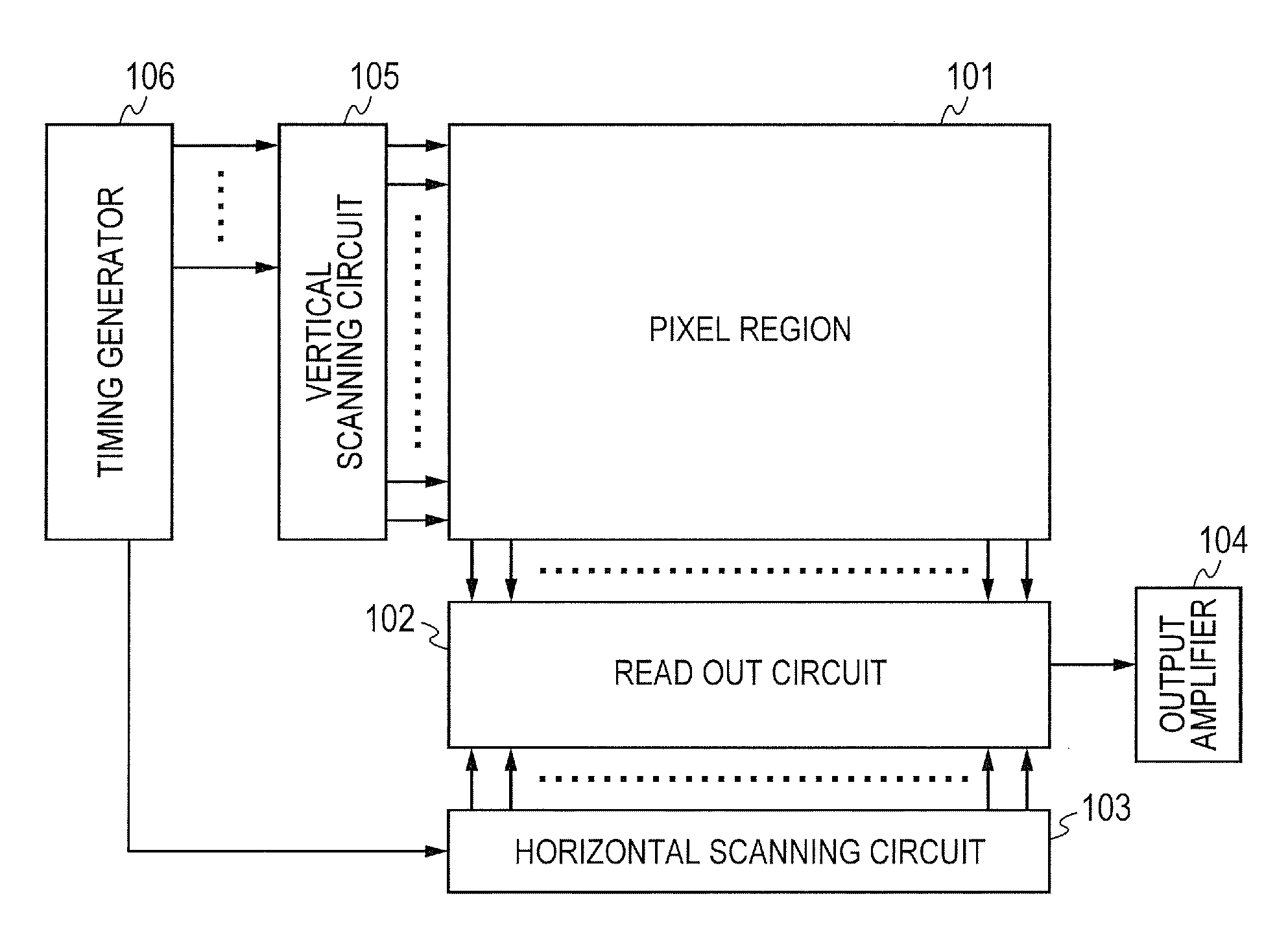
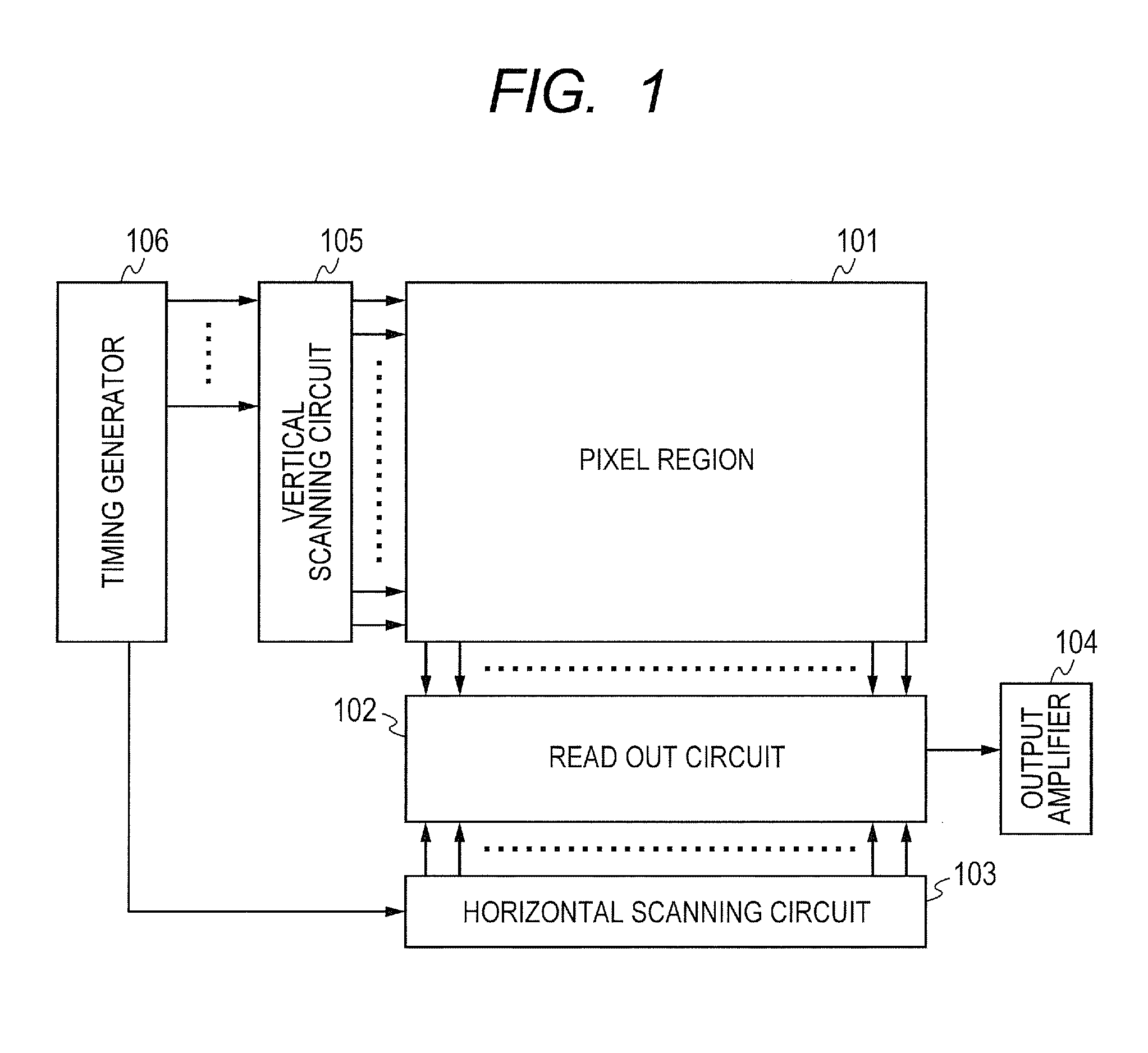
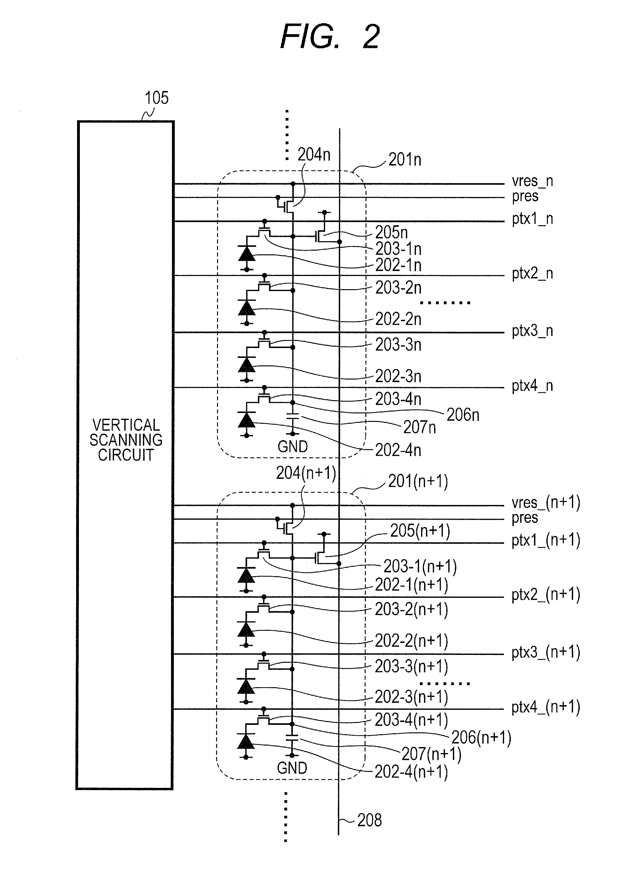
[0025]For the simplification, the illumination of an object is low in examples described in all embodiments of the present invention. FIG. 1 is a block diagram illustrating an example of configuration of an imaging apparatus according to a first embodiment of the present invention. FIG. 2 is a diagram illustrating a connection diagram of a pixel unit and a vertical scanning circuit according to the first embodiment of the present invention. A pixel region 101 of FIG. 1 includes a plurality of pixel units 201n, 201(n+1), and the like illustrated in FIG. 2 arranged in a matrix. The pixel unit 201n and the like include a plurality of pixels corresponding to a plurality of photodiodes 202-1n to 202-4n and the like. The pixel region 101 includes color filters (not illustrated) in a Bayer color array in each of the pixel units 201n and the like. A read out circuit 102 reads out pixel signals of pixels in the pixel region 101, row by row. A horizontal scanning circuit 103 successively outp...

second embodiment

[0064]In a second embodiment of the present invention, the same imaging apparatus as in the first embodiment is used to perform the reading out at different timing. FIG. illustrates timing and variation in the FD potential indicating a driving method of the imaging apparatus according to the second embodiment of the present invention. Differences between the present embodiment (FIG. 6) and the first embodiment (FIG. 5) will be described. At the times t1-1 to t10-1, the signal of the photodiode 202-1n of the first row of the pixel unit 201n is read out. At the times t1-2 to t10-2, the signal of the photodiode 202-2n of the second row is read out. A state B is executed at the times t11 to t13, and the first and second rows are horizontally transferred at the horizontal transfer period. After the end of the horizontal transfer, the signal of the photodiode 202-3n of the third row is read out at the times t1-3 to t10-3. The signal of the photodiode 202-4n of the fourth row is read out a...

third embodiment

[0067]FIG. 7 illustrates timing and variation in the FD potential indicating a driving method of the imaging apparatus according to a third embodiment of the present invention. In the present embodiment, after the signal of the photodiode 202-1 of the first row of the pixel unit 201n is read out at the times t1-1 to t10-1, the state B of the times t11 to t13 is performed, and the first row is horizontally transferred at the horizontal transfer period. After the signal of the photodiode 202-2n of the second row of the pixel unit 201n is read out at the times t1-2 to t10-2, the state B is performed at the times t11 to t13, and the second row is horizontally transferred at the horizontal transfer period. After the signal of the photodiode 202-3n of the third row of the pixel unit 201n is read out at the times t1-3 to t10-3, the state B is performed at the times t11 to t13, and the third row is horizontally transferred at the horizontal transfer period. Lastly, after the signal of the p...


PUM


Abstract

A driving method of an imaging apparatus comproses: horizontally transferring, by a horizontal scanning circuit, a signal based on a photoelectric conversion portion of a first pixel unit held in a signal holding capacitor to a common line; before ending of the horizontal transfer; applying, by a reset switch of a second pixel unit, a selection reset voltage to a floating diffusion region of the second pixel unit; and after the horizontal transfer, transferring, by a transfer switch of the second pixel unit, a signal of a photoelectric conversion portion of the second pixel unit to the floating diffusion region of the second pixel unit and amplifying, by an amplification transistor of the second pixel unit, a signal of the floating diffusion region of the second pixel unit to output the signal to an output line.

Description

BACKGROUND OF THE INVENTION[0001]1. Field of the Invention[0002]The present invention relates to an imaging apparatus and a driving method of the imaging apparatus.[0003]2. Description of the Related Art[0004]In recent years, an imaging apparatus including an amplifying portion at a pixel section is proposed. Japanese Patent Application Laid-Open No. 2008-219423 discloses a configuration in which a plurality of pixels shares one amplification transistor. The imaging apparatus disclosed in Japanese Patent Application Laid-Open No. 2008-219423 controls a voltage of a floating diffusion region (hereinafter, “FD”) as an input of the amplifying portion to select a pixel from which a signal will be read out.SUMMARY OF THE INVENTION[0005]The present inventors have found out that the voltage of the FD is not quickly stabilized when the pixel is selected in the conventional driving method of the imaging apparatus, and the voltage of the FD may continue to vary during a period after the selec...

Claims


Application Information

Patent Timeline
Patent Type & Authority Applications(United States)
IPC IPC(8): H01L27/146
CPCH01L27/14643H04N5/37457H04N5/378H04N5/3658H04N25/677H04N25/778H04N25/75
Inventor IWATA, KOICHIRONODA, TOMOYUKIAKIYAMA, TAKESHIMORITA, KAZUMICHISONODA, KAZUHIROYAMAMOTO, TAKURO
Owner CANON KK
Why Eureka
Try Eureka