Pulse detonation combustor with plenum

a combustor and plenum technology, applied in the direction of combustion types, intermittent jet plants, lighting and heating apparatus, etc., can solve the problems of pulsed operation in practicable pde applications, and achieve the effect of prolonging the duration of the plateau and the blowdown time and prolonging the blowdown tim

Inactive Publication Date: 2013-02-21
GENERAL ELECTRIC CO
View PDF1 Cites 27 Cited by
  • Summary
  • Abstract
  • Description
  • Claims
  • Application Information

AI Technical Summary

Benefits of technology

[0004]The inventors have solved the problem of lowering the peak of the pressure pulse and extending the duration of the plateau and blowdown time for a PDC by providing at least one plenum along the length of the PDC. The plenum can either be upstream or downstream of the fuel injection port and ignition source. The plenum can be used instead of, or in conjunction with, a downstream exit nozzle that also assists in extending the blowdown time.

Problems solved by technology

The challenge is that practical PDE applications require pulsed operation due to the unsteady nature of detonations.

Method used


Image

  • Pulse detonation combustor with plenum
  • Pulse detonation combustor with plenum
  • Pulse detonation combustor with plenum

Examples


Embodiment Construction

[0018]The present invention will be explained in further detail by making reference to the accompanying drawings, which do not limit the scope of the invention in any way.

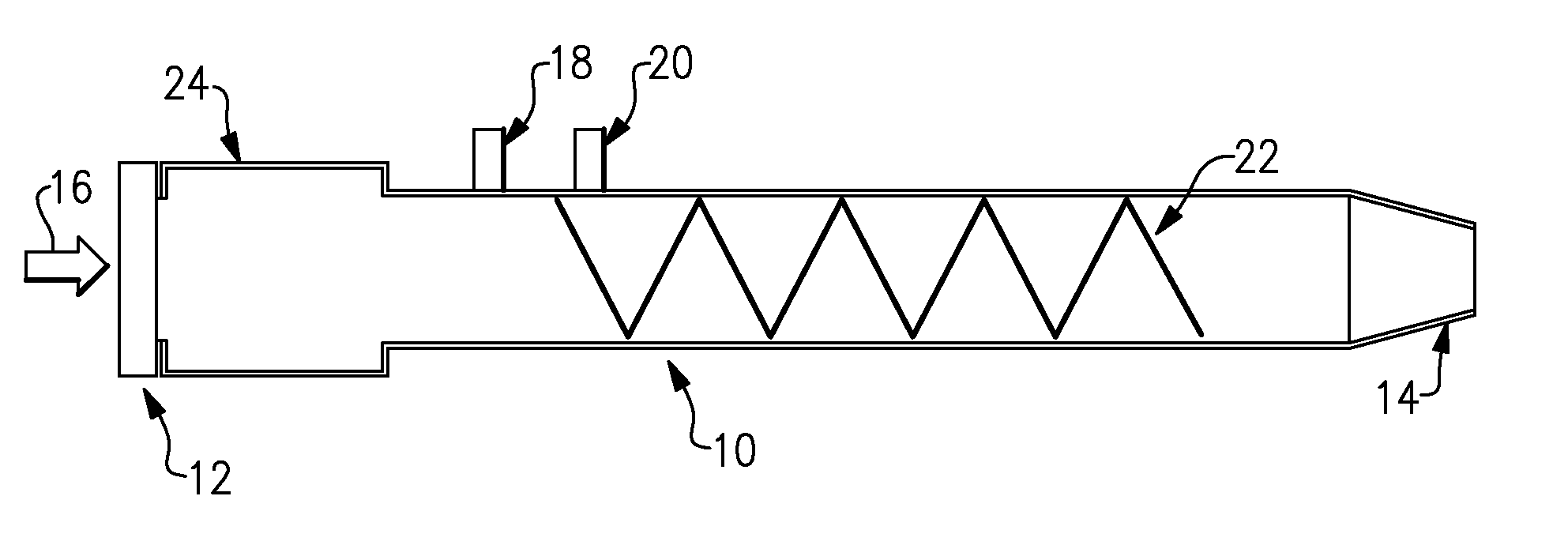
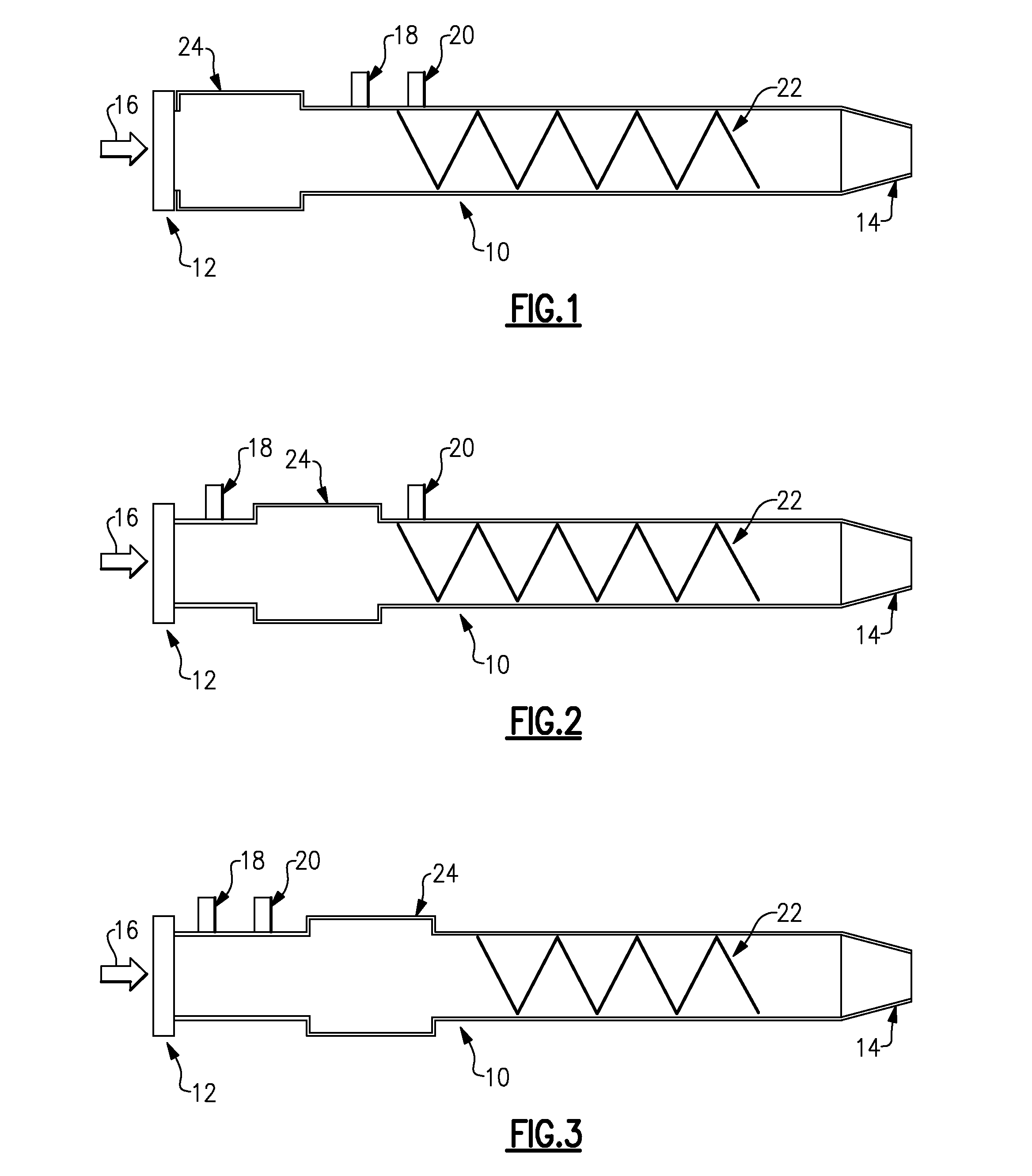
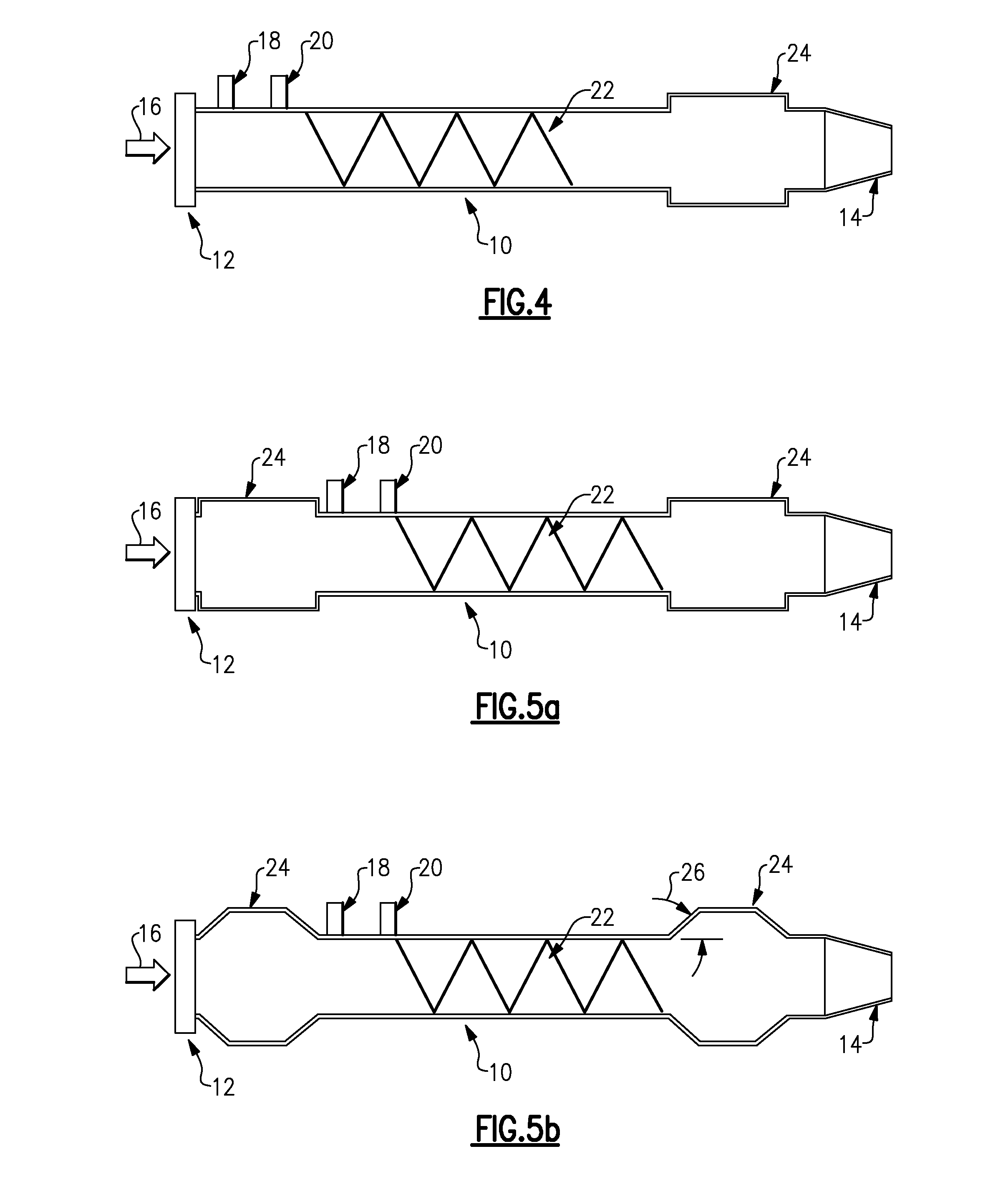
[0019]FIG. 1 depicts a pulse detonation combustor (PDC) 10 having an air valve 12 at one end and an exit nozzle 14 at an opposite end according to an embodiment of the invention. In the illustrated embodiment, the exit nozzle 14 is a converging nozzle. However, it will be appreciated that the exit nozzle 14 could also be a converging / diverging nozzle, rather than a converging nozzle. The air valve 12 can be of any type: disk, rotating can, poppet, sleeve valve, and the like. Airflow 16 for the combustor 10 can be provided from any conventional primary airflow source (not shown), for example, from a compressor stage of an engine (not shown), or comparable source. Fuel can be supplied to the combustor 10 by means of a conventional fuel injector port 18. The fuel injector port 18 may be controlled by any known or conv...


PUM


Abstract

A pulse detonation combustor includes at least one plenum located along the length of the pulse detonation combustor. The plenum can be located: 1) proximate an air valve; 2) between a fuel injection port and an ignition source; 3) downstream of both the fuel injection port and the ignition source; and 4) proximate an exit nozzle of the pulse detonation combustor. In addition, the pulse detonation combustor can have multiple plenums, for example, proximate the air valve and proximate the exit nozzle. The location and dimensions of the plenum can be selectively adjusted to control mechanical loading on the wall, the velocity of fluid flowing within the combustor, and the pressure generated by the pulse detonation combustor.

Description

BACKGROUND OF THE INVENTION[0001]This invention relates to pulse detonation systems, and more particularly, to a pulse detonation combustor (PDC) with at least one plenum for lowering the peak of the pressure pulse and extending the duration of the plateau and blowdown time.[0002]With the recent development of pulse detonation combustors (PDCs) and pulse detonation engines (PDEs), various efforts have been underway to use PDC / Es in practical applications, such as combustors for aircraft engines and / or as means to generate additional thrust / propulsion in a post-turbine stage. Further, there are efforts to employ PDC / E devices into “hybrid” type engines that use a combination of both conventional gas turbine engine technology and PDC / E technology in an effort to maximize operational efficiency.[0003]One of the key advantages of a pulse detonation engine (PDE) is the pressure-rise combustion that leads to increased performance by attaining a quasi-constant volume thermodynamic cycle. T...

Claims


Application Information

Patent Timeline
Patent Type & Authority Applications(United States)
IPC IPC(8): F02K7/02
CPCF23C15/00F23R7/00
Inventor RASHEED, ADAMTANGIRALA, VENKATJOSHI, NARENDRAKENYON, ROSS
Owner GENERAL ELECTRIC CO
Why Eureka
Try Eureka