
Method for surface treatment of a die-casting die

a die-casting die and surface treatment technology, applied in the direction of manufacturing tools, foundry patterns, moulding apparatus, etc., can solve the problems of shallow depth of nitrogen diffusion layer, degrade the dimensional accuracy of cast products, etc., and achieve excellent abrasion resistance, high hardness, and high residual stress.

Inactive Publication Date: 2013-02-21
SINTOKOGIO LTD
View PDF2 Cites 12 Cited by
  • Summary
  • Abstract
  • Description
  • Claims
  • Application Information

AI Technical Summary

Benefits of technology

The present invention relates to a method for manufacturing a die-casting die with improved abrasion resistance and heat check resistance. By eliminating a nitride compound layer in the die, the inventors found that the decomposition of the uppermost layer by a thermal process increased the amount of nitrides in the die, which improved its strength. The method involves a step of decomposing the compound at a lower temperature than the nitriding process, resulting in higher hardness and compression residual stress. This invention allows for the production of stronger die-casting dies.

Problems solved by technology

The heat checks may develop into a crack or cracks to damage the die, and the abrasion may degrade the dimensional accuracy of the cast product.
However, the depth of the nitrogen diffusion layer also becomes shallow.

Method used


Image

  • Method for surface treatment of a die-casting die
  • Method for surface treatment of a die-casting die
  • Method for surface treatment of a die-casting die

Examples


Embodiment Construction

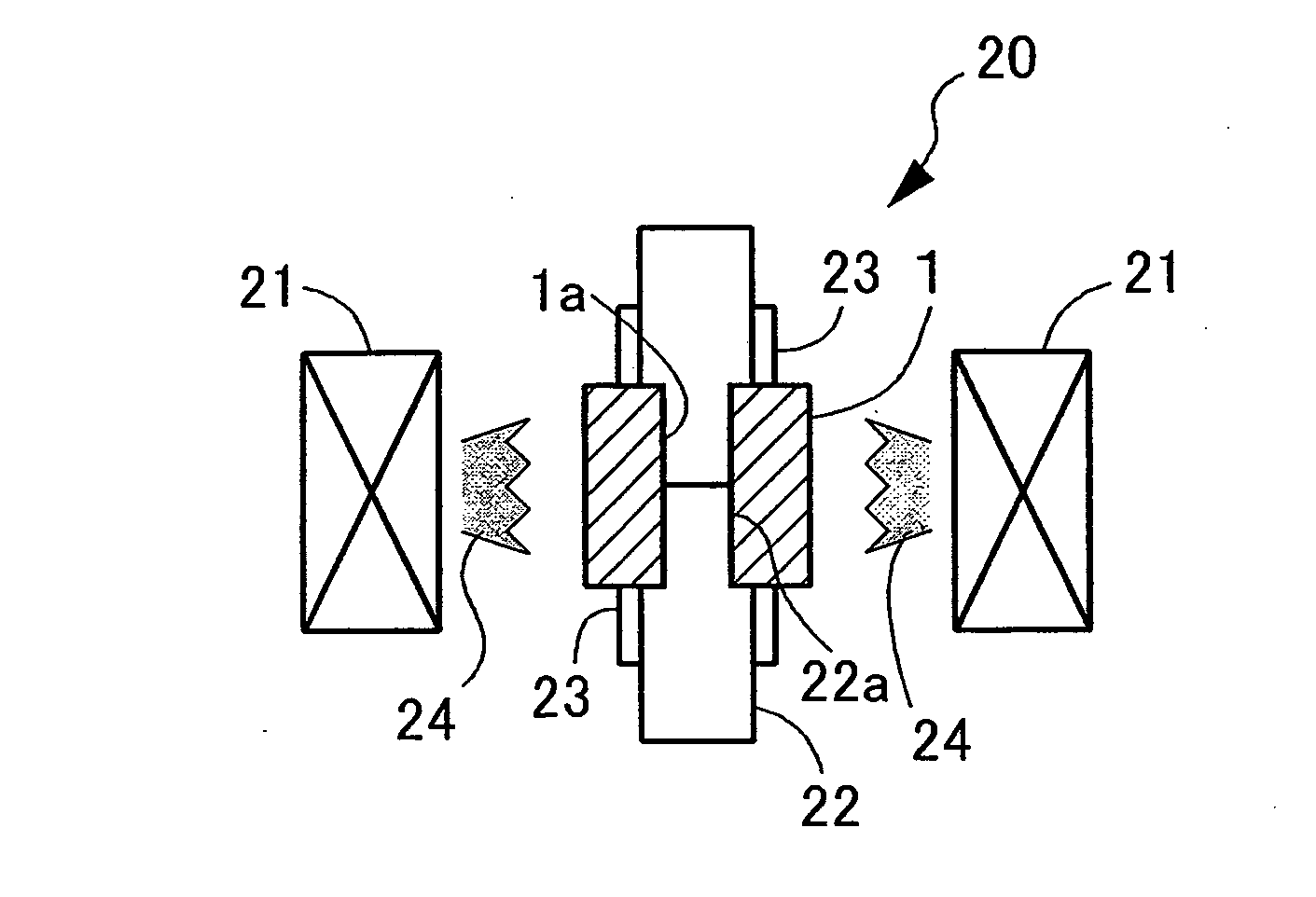
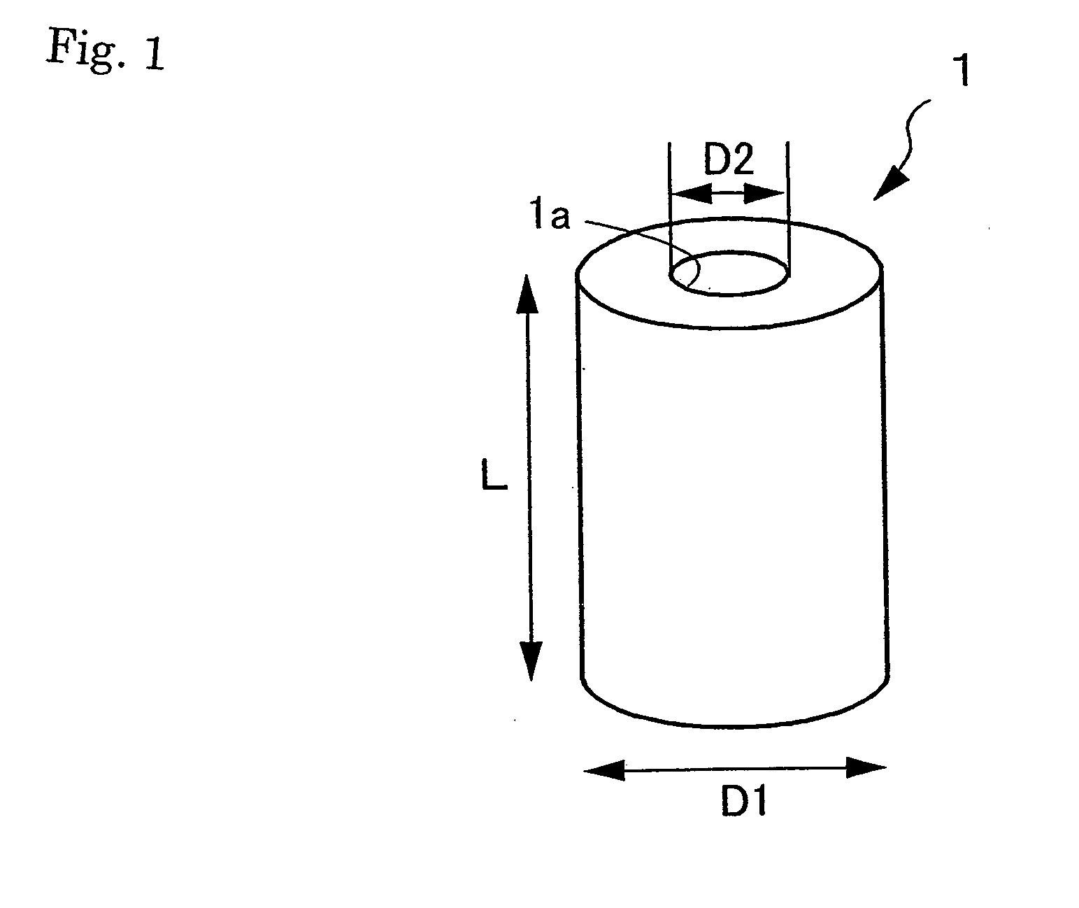
[0027]On the method for surface treatment of the die-casting die of the present invention, the details will be explained with reference to the result of the verification test as indicated in FIGS. 1 to 8. In the verification tests, cylindrical specimens 1 (see FIG. 1) each corresponding to a die-casting die are prepared and various surface treatments are then carried out on them to evaluate them.

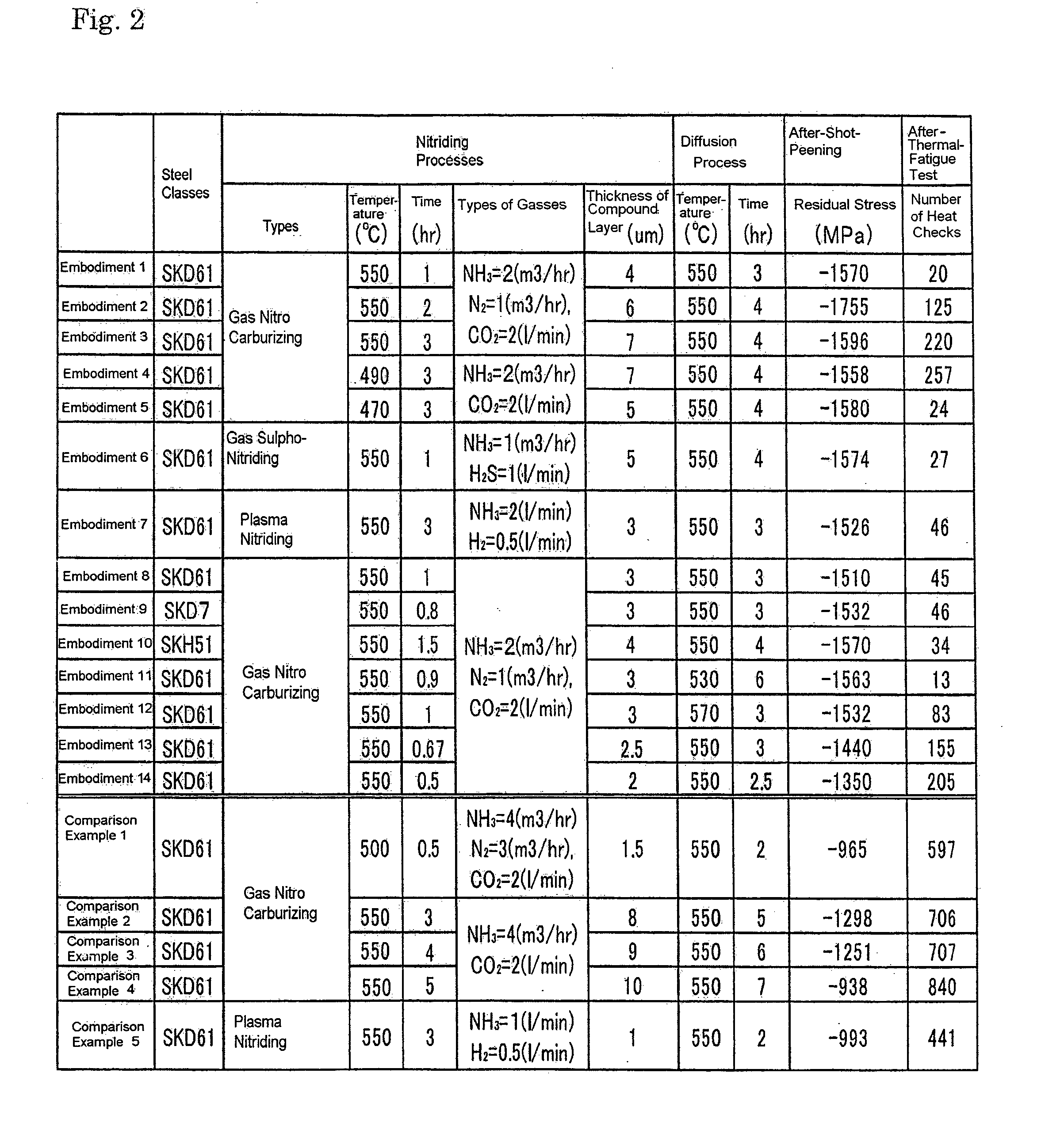
[0028]Cylindrical specimens 1 having an outer diameter D1=15 mm, an inner diameter D2=3 mm, and a length L=20 mm are prepared. Each specimen 1 is machined from a round bar stock of Japanese Industrial Standards (JIS), the steel material of an alloy toll SKD 61 equivalency. Instead of the SKD 61 equivalency, the specimens 1 in the ninth embodiment and the tenth embodiment are machined from round bar stocks of JIS SKD 7 equivalency and a steel material of an alloy toll SKH51 equivalency. The steel classes of the embodiments and comparison examples are described and compiled in FIG. 2.

[0029]Eac...


PUM

PropertyMeasurementUnit
thicknessaaaaaaaaaa
diameteraaaaaaaaaa
temperaturesaaaaaaaaaa

Abstract

The present invention is to provide a method for surface treatment that substantially provides no nitride compound layer that causes heat checks and abrasion to a die, while nitride is introduced in large quantities into the die internally, and as a result a die-casting die with excellent heat check resistance and excellent abrasion resistance can be produced. The method comprises a step of a nitriding process for forming on an aesthetic surface of the die-casting die a nitrided layer that includes at least a compound layer composed of a nitrogen compound by introducing gas containing at least ammonia gas to a heating furnace, a step of decomposing the compound by exhausting the ammonia gas from the heating furnace and for introducing ambient gas to the heating furnace, to carry out a thermal process to decompose the nitrogen compound, and a step of processing a shot peening process on the aesthetic surface of the die. The thickness of the compound layer contained in the nitrogen layer that is formed in the step of nitriding process is within the range of from 2∫m to 7∫m.

Description

TECHNICAL FIELD [0001]This invention relates to a method for the surface treatment of a die-casting die is provided by applying the compression residual stress in an aesthetic surface of the die-casting die using a shot-peening process.BACKGROUND OF THE INVENTION [0002]In a die-casting molding in which a casting cycle that includes pouring a molten metal, solidification, and stripping a cast product is repeated, small heat checks on an aesthetic surface of a die-casting the can be readily produced by a thermal history to be given by the casting cycles. Thus abrasions caused by mechanical contacts can be readily produced. The heat checks may develop into a crack or cracks to damage the die, and the abrasion may degrade the dimensional accuracy of the cast product. Therefore, to enhance heat check resistance and abrasion resistance to extend a product's life, processes such as a surface nitriding process-to enhance the hardness of the aesthetic surface of the die and a shot-peening pr...

Claims


Application Information

Patent Timeline
Patent Type & Authority Applications(United States)
IPC IPC(8): B22C9/12B22D17/22
CPCC23C8/24C23C8/26C23C8/28C23C8/30C23C8/80C23C8/34C23C8/36C23C8/38C23C8/32
Inventor HIRAOKA, YASUSHIKOBAYASHI, YUJI
Owner SINTOKOGIO LTD
Learn More