Dual-Polarized Microstrip Antenna

a microstrip antenna and microstrip technology, applied in the field of antennas, can solve the problems of low work efficiency, low work efficiency, low vertical hpbw, low gain, etc., and achieve the effect of effectively expanding the frequency bandwidth of the antenna, excellent polarization isolation, and small area

Inactive Publication Date: 2013-02-21
ZHUANG KUNJIE
View PDF2 Cites 204 Cited by
  • Summary
  • Abstract
  • Description
  • Claims
  • Application Information

AI Technical Summary

Benefits of technology

[0060]at least one dielectric layer, i.e. a first dielectric layer, is arranged, and it is preferred that the dielectric layer is a resonant dielectric layer of air or a layer of other optimization resonant materials; the dielectric layer is positioned between the first metal radiating patch and the ground metal layer; it is preferred that the thickness of the dielectric layer ranges from 1 to 20 mm, particularly from 4 to 10 mm; and the first dielectric layer is an important component for tuning the VSWR of an antenna source port;
[0061]at least one set of bipolar excitation microstrip lines is arranged, it is preferred that the front ends of the two excitation microstrip lines are linear, and it is preferred that the front end of each excitation microstrip line is vertical to the cross arm “-” of one H-shaped excitation micro-slot, and the front ends pass through the middle points of the cross arms “-” of the respective H-shaped excitation micro-slots; the front ends of the two excitation microstrip lines are discretely vertical for the purpose of guaranteeing the polarization isolation of the dual-polarized antenna, and excellent polarization isolation can lead one dual-polarized antenna to be used as two independent antennas; the distance and perpendicularity between the two discrete front ends which are not in contact are among the key parameters affecting the polarization isolation of the dual-polarized antenna, and are preferred to range from 3 to 8 mm and to be 90° respectively;
[0062]it is preferred that a second dielectric layer is arranged; it is preferred that the second dielectric layer is a resonant dielectric layer, particularly a resonant dielectric layer of air or a layer of other optimization resonant materials; it is preferred that the second dielectric layer is a slot cavity, which is preferred to be a cavity formed above the ground metal layer by the metal support for system ground; it is preferred that the depth of the slot cavity ranges from 1 to 10 mm; the second dielectric layer is a tuning component participating in frequency band matching and widening, and if the first and the second dielectric layers are air layers and no other radiating patches or components are arranged above the second dielectric layer, the first and the se

Problems solved by technology

The present microwave antenna, with the defects of low work efficiency, clumsiness and difficulty in installation and maintenance, is far from meeting the requirements of the development of mobile communication technology for antenna technology.
First, products publicly advertised, presented, sold and applied at domestic and abroad cannot meet the technical requirements in operators' new-generation communication standards.
In addition, present products have the defects of large size, heavy w

Method used


Image

  • Dual-Polarized Microstrip Antenna
  • Dual-Polarized Microstrip Antenna
  • Dual-Polarized Microstrip Antenna

Examples


embodiment 1

l-Polarized Antenna

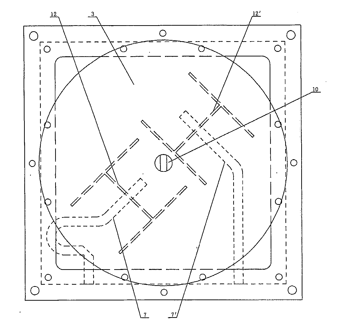
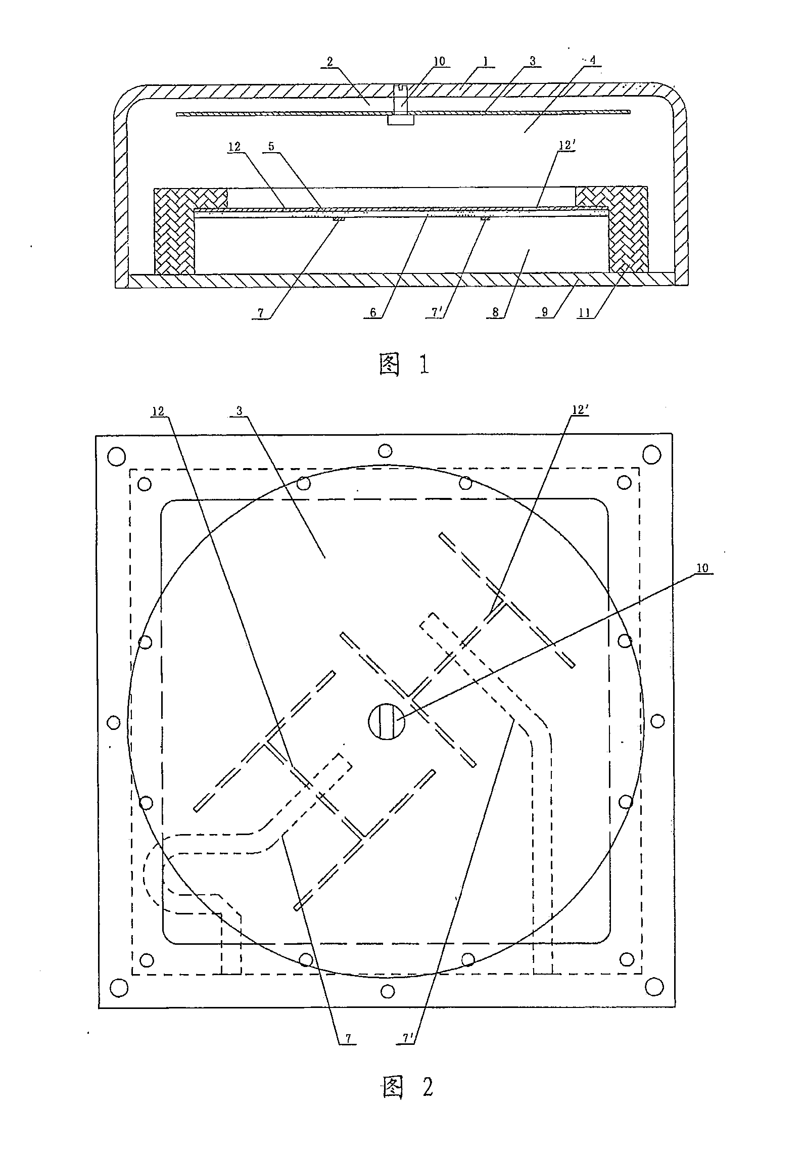
[0127]FIG. 1 and FIG. 2 show a small microwave low-band multi-frequency high-gain dual-polarized microstrip antenna according to this embodiment (a TD-SCDMA dual-polarized antenna; TD-SCDMA frequencies of CMCC under a 3G license: 1,880-1,920 MHz and 2,010-2,025 MHz), wherein a first air dielectric layer 2, a first metal radiating patch 3, a second air dielectric layer 4, a ground metal patch 5, a first dielectric substrate 6, bipolar excitation microstrip lines 7, 7′, a third air dielectric layer 8 and a metal reflection baseplate 9 are sequentially arranged in an antenna cover 1 from top to bottom. The first metal radiating patch 3 is connected with the antenna cover 1 through a screw 10. The ground metal patch 5 covers the upper end surface of the first dielectric substrate 6, and is fixedly connected with a hollow metal support 11 which is fixed on the metal reflection baseplate 9. The bipolar excitation microstrip lines 7, of which the front ends are orthogona...

embodiment 2

TD-LTE Antenna

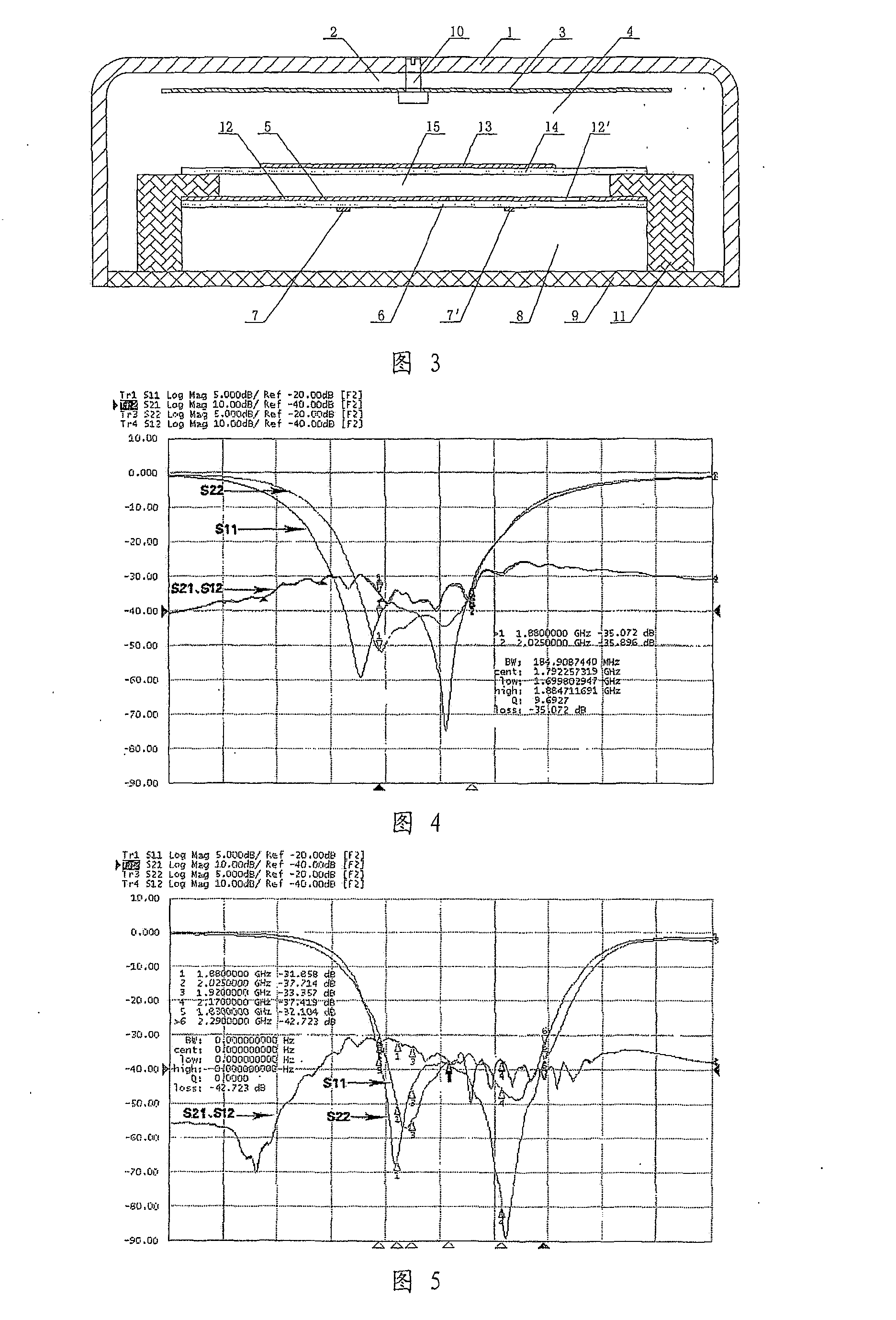
[0131]FIG. 3 shows a small microwave low-band multi-frequency high-gain dual-polarized microstrip antenna according to this embodiment (coverage: TD-SCDMA and TD-LITE frequencies; WCDMA frequencies: 1,920-1,980 MHz and 2,110-2,170 MHz; TD-SCDMA frequencies: 1,880-1,920 MHz and 2,010-2,025 MHz), which is based on Embodiment 1 and further includes a second metal radiating patch 13 and a second dielectric substrate 14 in the second air dielectric layer 4. The lower end surface of the second metal radiating patch 13 is jointed with the upper end surface of the second dielectric substrate 14 to form as a whole, which is then fixedly connected with the hollow metal support 11 fixed on the metal reflection baseplate 9 to form a fourth air dielectric layer 15 below the second dielectric substrate 14. This configuration helps further enlarge the working frequency bandwidth of the antenna. The second metal radiating patch 13 is circular, so that the VSWR at the I / O port of the a...

embodiment 3

olarized Microstrip Antenna with Three Metal Radiating Patches

[0134]FIG. 6 shows a small dual-polarized microstrip antenna with three metal radiating patches based on Embodiment 2, in which a third metal radiating patch 18 and a third dielectric substrate 17 are further arranged between the second metal radiating patch 13 and the first metal radiating patch 3. The third metal radiating patch 18 is parallel to the first metal radiating patch 3 and insulated from the second metal radiating patch 13 and the hollow metal support 11. The lower end surface of the third metal radiating patch 18 is jointed with the upper end surface of the third dielectric substrate 17 to form as a whole, which is then fixedly connected with an insulation support 19 fixed on the second dielectric substrate 14 to form a fifth air dielectric layer 16 below the third dielectric substrate 17.

[0135]Test results prove that the working bandwidth of the antenna according to Embodiment 3 is further enlarged without ...


PUM


Abstract

A dual-polarized microstrip antenna includes: at least one metal radiating patch, i.e. a first metal radiating patch; at least one ground metal layer whereon excitation micro-slots are etched; at least one dielectric layer, i.e. a first dielectric layer it is preferred that the dielectric layer is a resonant dielectric layer such as a resonant dielectric layer of air or other layers of optimization resonant materials; at least one set of bipolar excitation microstrip lines; the dielectric layer is between the first metal radiating patch and the ground metal layer. The dual-polarized microstrip antenna of multi-layer radiation structure is designed in a relatively small volume, which effectively saves the cost of antenna installation and maintenance, and is widely applied in the fields of mobile communication and internet technology.

Description

TECHNICAL FIELD[0001]The invention relates to an antenna device, in particular a small microwave low-band multi-frequency high-gain dual-polarized microstrip antenna. Embodiments disclose a microwave antenna with a multi-excitation and multi-layer tuning mechanism, belonging to the technical field of antennas for signal transmission and mobile communication as well as the wireless Internet.PRIOR ART[0002]With the rapid development of mobile communication and Internet technologies, a good number of new hot technologies have emerged in recent years, such as mobile Internet, WLAN, MAN and Internet of Things, indicating an urgent need to adopt the multi-antenna technology (e.g. MIMO technology) to enhance the quality and speed of data transmission of wireless communication channels. The present microwave antenna, with the defects of low work efficiency, clumsiness and difficulty in installation and maintenance, is far from meeting the requirements of the development of mobile communicat...

Claims


Application Information

Patent Timeline
IPC IPC(8): H01Q13/10
CPCH01Q9/0428H01Q5/50H01Q21/065H01Q9/0457H01Q9/0414H01Q1/24H01Q13/08
Inventor ZHUANG, KUNJIE
Owner ZHUANG KUNJIE
Why Eureka
Try Eureka