Method and apparatus to improve efficiency in the use of resources in data center

a data center and resource efficiency technology, applied in the field of storage systems, can solve the problems of short bandwidth of interconnection, difficult detection of virtualized environment monitoring, and current approach problems, so as to improve the efficiency in the use of resources, improve the efficiency of resource use, and improve the effect of resource utilization

Inactive Publication Date: 2013-02-21
HITACHI LTD
View PDF0 Cites 30 Cited by
  • Summary
  • Abstract
  • Description
  • Claims
  • Application Information

AI Technical Summary

Benefits of technology

[0006]Exemplary embodiments of the invention improve the efficiency in the use of resources in a data center. The proposed approach checks the physical configuration of virtualized resources and specifies the inefficient configuration. Then it provides a migration plan which improves the efficiency in the use of the resources in the data center and executes the plan if the plan satisfies the service level objective. This approach is used for efficient deploy of firmware of server or storage in the data center. It is also used for efficient deploy of the path of virtual machine or application in the data center.

Problems solved by technology

The current approach has problems.
It is difficult to detect to monitor the virtualized environment.
As a result, the following problems can occur: high performance resources are used for low priority application, some virtual machine cannot maintain SLO (Service Level Objective), the bandwidth of interconnect becomes short, etc.

Method used


Image

  • Method and apparatus to improve efficiency in the use of resources in data center
  • Method and apparatus to improve efficiency in the use of resources in data center
  • Method and apparatus to improve efficiency in the use of resources in data center

Examples


first embodiment

[0041]The first embodiment discloses how to improve the efficiency in the use of resources in a data center.

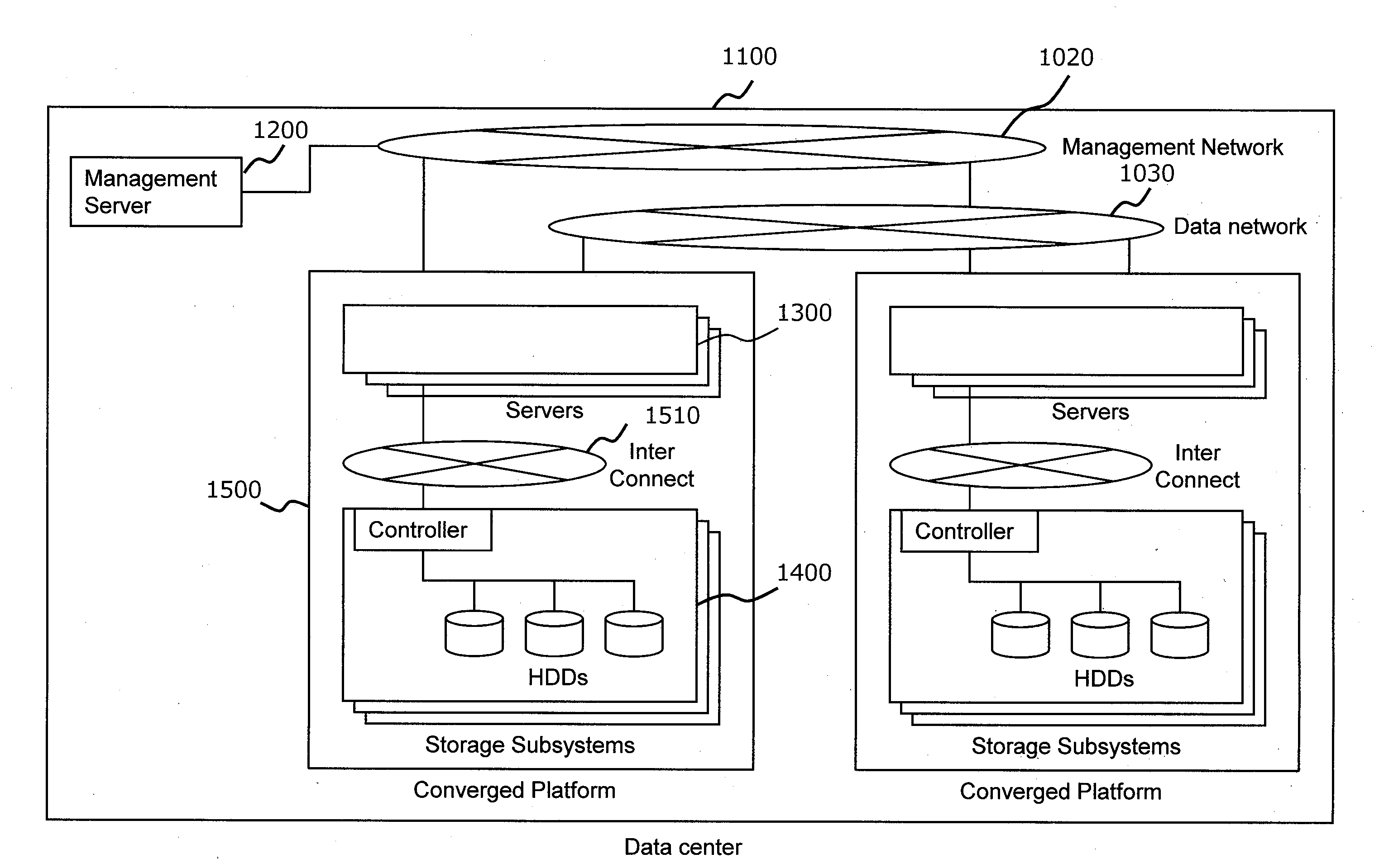
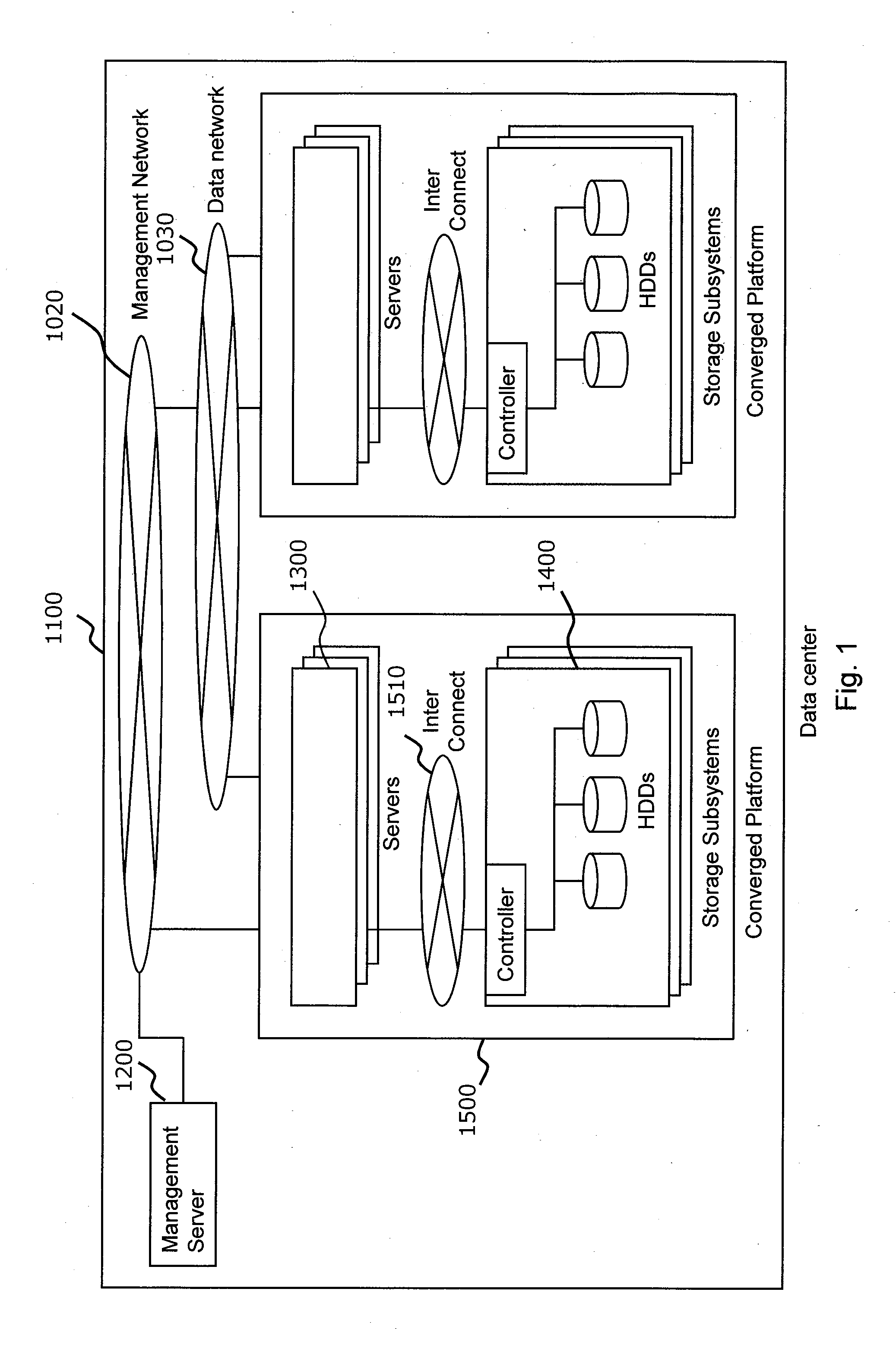
[0042]FIG. 1 illustrates an example of a hardware configuration of a data center system in which the method and apparatus of the invention may be applied according to the first embodiment. A data center 1100 includes a Converged Platform 1500 and a Management Server 1200. The Converged Platform 1500 is one of the hardware configurations which include servers, networks, and storages all-in-one. The Converged Platform 1500 is configured with Servers 1300, Storage Subsystems 1400, and Interconnect 1510. Multiple Converged Platforms 1500 are connected via a Data Network 1030. The Converged Platforms 1500 and Management Server 1200 are connected via a Management Network 1020. In this embodiment, the Management Network 1020 and Data Network 1030 are separate. This specific configuration does not limit the scope of the present invention.

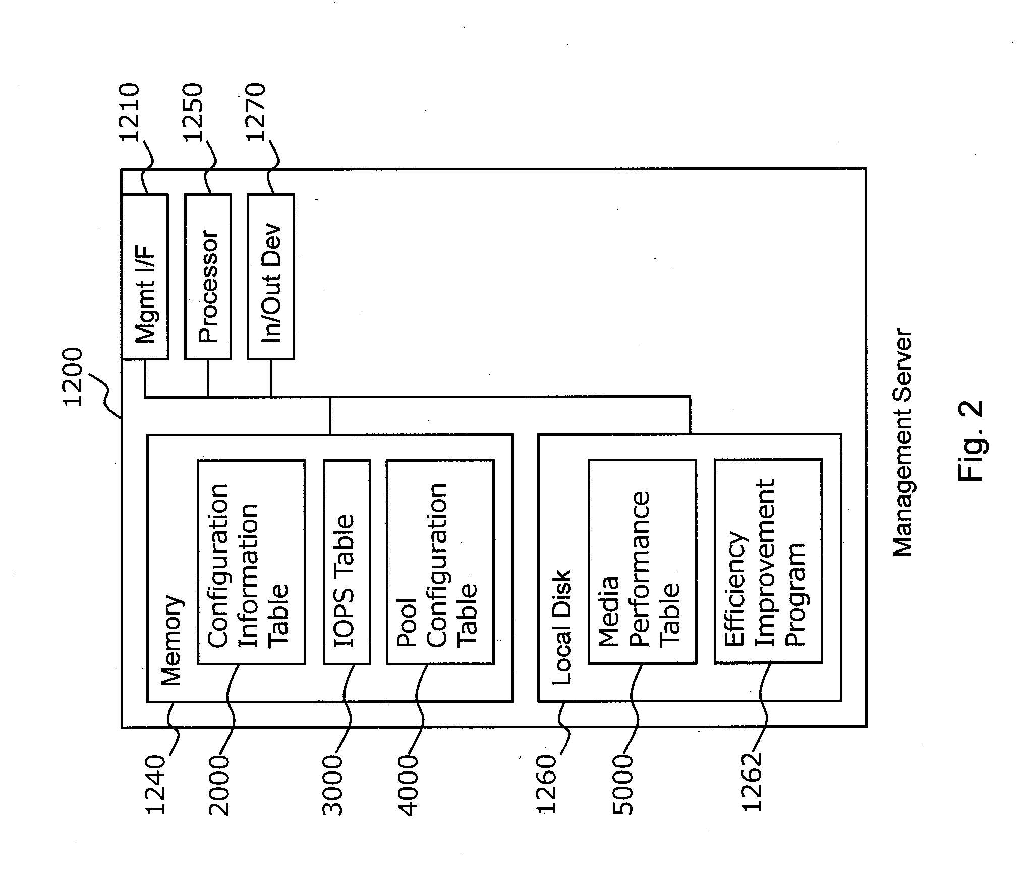
[0043]FIG. 2 shows an example of the configurat...

second embodiment

[0061]The target configuration of the first embodiment is a converged platform. Even if the target configuration is not a converged platform, this invention can be applied. The second embodiment discloses how to improve efficiency in the use of resources in a data center which has a non-converged platform environment. The system configuration and procedure are almost the same as those of the first embodiment. The following explains only the differences with the first embodiment.

[0062]FIG. 12 illustrates an example of a hardware configuration of a data center system according to the second embodiment. The data center 1101 includes Servers 1300, Storage Subsystems 1400, and Management Server 1200. The Servers 1300 and Storage Subsystems 1400 are connected via a Data Network 1030. This network is typically a SAN (Storage Area Network), but it is not limited to this. The Servers 1300, Storage Subsystems 1400, and Management Server 1200 are connected via a Management Network 1020. This n...

third embodiment

[0068]The target of the second embodiment is one data center. Even if the target configuration is not one data center, this invention can be applied. The third embodiment discloses how to improve the efficiency in the use of resources in a multi data centers environment. The system configuration and procedure are almost the same as those of the second embodiment. The following discusses only the differences with the second embodiment.

[0069]FIG. 17 illustrates an example of a hardware configuration of a multi data centers system according to the second embodiment. The system shown has two data centers, but the invention is not limited to two data centers. Each data center 1100 includes Servers 1300 and Storage Subsystems 1400. One Management Server 1200 is placed at one data center, but the invention is not limited to one management server. Multiple management servers can be provided. The Servers 1300 and Storage Subsystems 1400 are connected via a Data Network 1030. This network is ...


PUM


Abstract

A method of managing use of resources in data center comprises: determining whether first storage subsystem includes a virtual volume or a storage pool that uses a physical volume of second storage subsystem and, if yes, migrating the physical volume to first storage subsystem; determining whether any storage subsystem includes a virtual volume created directly from a physical volume and, if yes, migrating the virtual volume to another virtual volume provisioned from the storage pool of the storage subsystem; and determining whether all virtual volumes satisfy a preset service level objective and, if no, then selecting a virtual machine which has a smallest virtual machine disk file and selecting a storage pool having a largest free space, and then selecting a virtual volume of the storage subsystem which has the selected storage pool and migrating the virtual machine disk file of the selected virtual machine to the selected virtual volume.

Description

BACKGROUND OF THE INVENTION[0001]The present invention relates generally to storage systems and, more particularly, to method and apparatus to improve the efficiency in the use of resources in a data center.[0002]Virtualization technology has become mature in data center. Virtualized server and virtualized application can be used without considering the limitation of physical resources such as server and storage. In the configuration of the data center, the components of the data center tend to have scale-out architecture. These components are connected by high-speed interconnect in general. Multiple data centers work together, forming a data center federation. In data center operation, Self Service Portal has become mainstream. Resource provisioning is done by service user, not IT administrator. Computing resource and storage resource provide resource pools. Service users can provision their resources from the pool in a flexible manner. For example, US2010 / 0040058 discloses a serve...

Claims


Application Information

Patent Timeline
Patent Type & Authority Applications(United States)
IPC IPC(8): G06F9/455
CPCG06F3/0607G06F3/0647G06F3/067G06F9/45533G06F9/5083H04L67/1097H04L67/34G06F9/5077
Inventor EMARU, HIRONORI
Owner HITACHI LTD
Why Eureka
Try Eureka