
Heat transfer bridge

a heat transfer bridge and heat transfer technology, applied in the direction of basic electric elements, semiconductor devices, lighting and heating apparatus, etc., can solve the problems of reducing the insulating properties of materials, affecting the operation of transformers, and aging of insulating materials, so as to improve the cooling effect of transformers, increase the capacity of operating transformers, and improve the effect of cooling

Inactive Publication Date: 2013-02-28
LIVINGSTON TROY W
View PDF7 Cites 17 Cited by
  • Summary
  • Abstract
  • Description
  • Claims
  • Application Information

AI Technical Summary

Benefits of technology

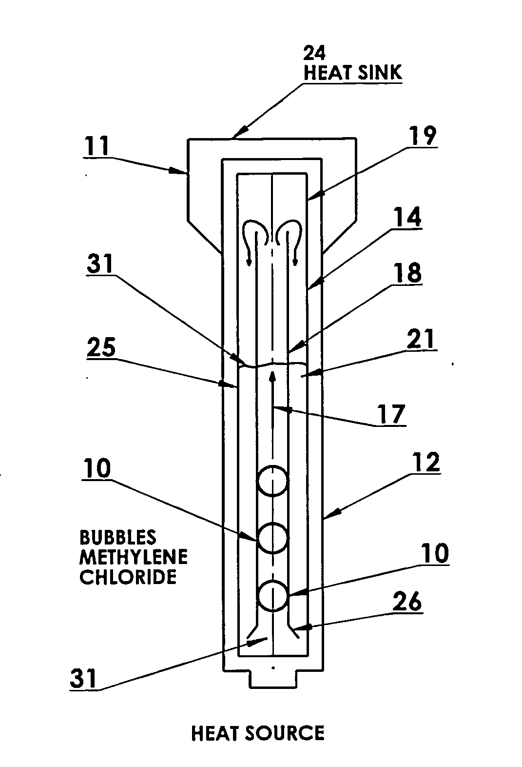
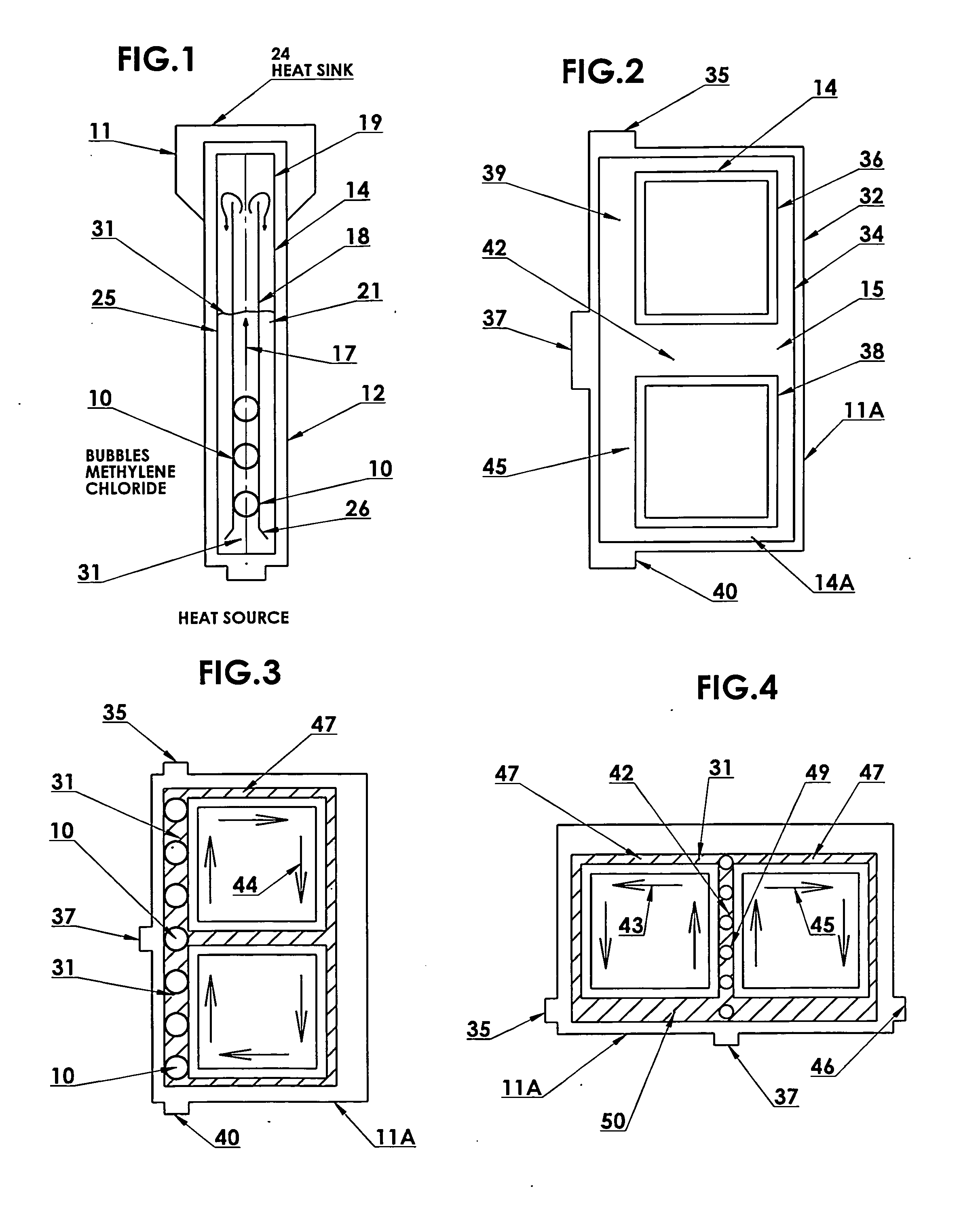
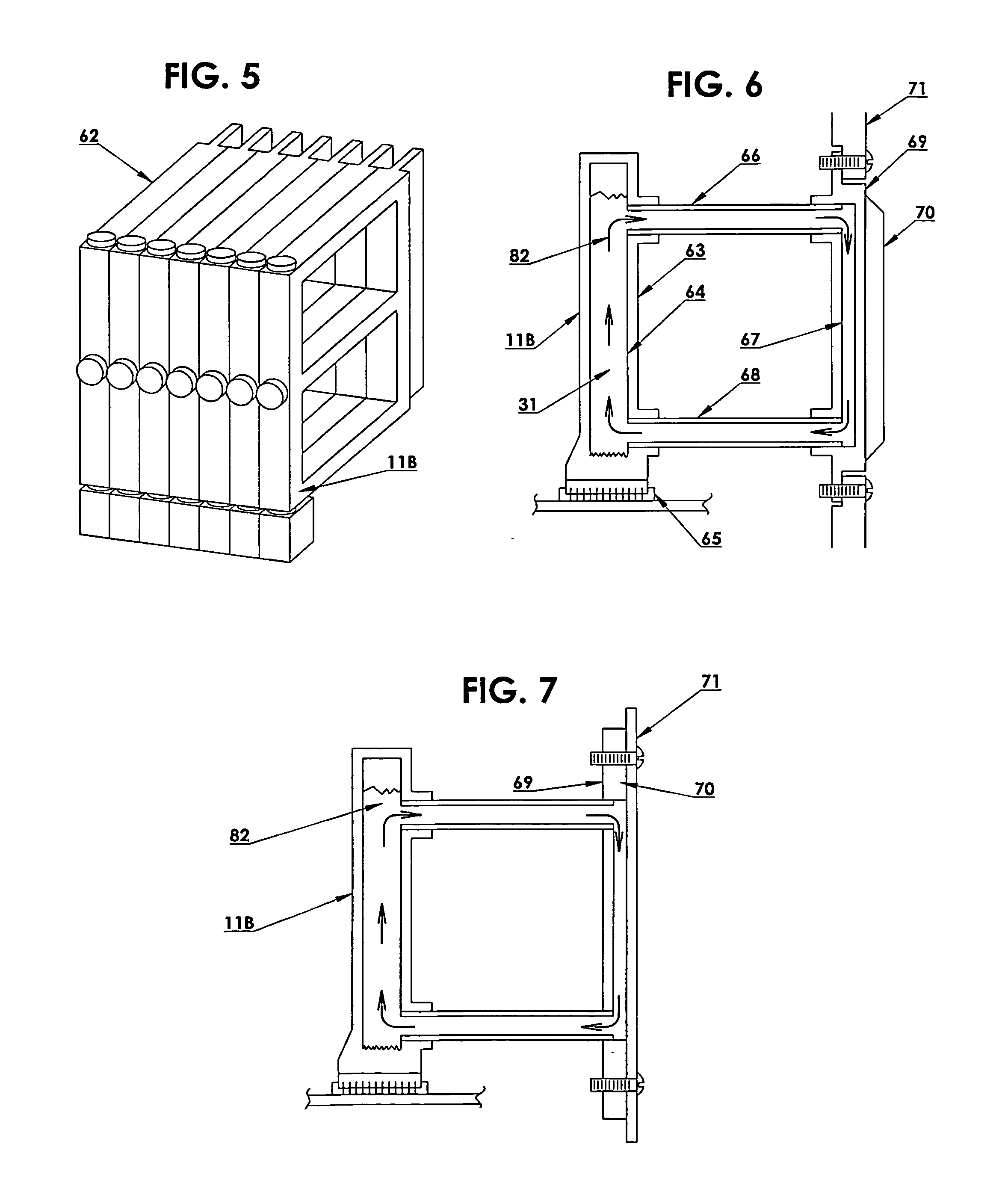
The present invention provides a system and method for efficiently cooling electronic components, such as circuit boards and IC chips, which will allow for the design of smaller and lighter electronic systems. Additionally, the invention provides a way to cool power line transformers without replacing them, increasing their output and improving their performance. The invention uses a passive transfer pump to rapidly remove thermal energy from heat sources to heat sink areas using a liquid carrying a metallic slurry, which has been found to be multiple times more effective in transferring and conveying heat than fluorocarbon fluids. The invention also includes a heat transfer bridge that can be retrofitted onto existing transformers or included in the design of new transformers, ensuring continued safe and reliable operation.

Problems solved by technology

Continuous transformer operation at elevated temperatures therefore results in faster aging of the insulating material with a consequent reduction of the insulating properties of the material.
Reduction or loss of the insulating properties of the material results in the failure of the transformer.

Method used


Image

  • Heat transfer bridge
  • Heat transfer bridge
  • Heat transfer bridge

Examples


Embodiment Construction

[0052]As alluded to above, one of the problems for developing circuit boards and IC chips, is the need for dissipating the heat generated by the components which operate at higher output / wattage. Further a problem for dissipating heat from circuit boards and IC chips is that the boards and chips are mounted in various orientations and in environments which may restrict air flow. The restricted and oft times minimal air flow will reduce the cooling capacity of hot surface and heat sinks / dissipating structure. The electronic junctions used in circuit boards are very small, therefore to be effective as a heat dissipation module, a module heat must efficiently absorb and dissipate heat energy from this small area.

[0053]It has been found that liquid cooling for circuit boards and IC chips is one of the most effective ways of cooling these components. It is standard practice to utilize pumps and compressors and refrigeration cycles to provide the liquid flow in a closed loop to carry the ...


PUM


Abstract

A heat transfer bridge for absorbing heat from electronic circuits and electrical distribution transformers to thereby cool said components is disclosed. The heat transfer bridge includes a passive pump for pumping a fluid having a low boiling point that readily creates bubbles when heated to its boiling point. The bubbles are directed via selected flow paths to effectively push or drive the fluid from adjacent a heat source such as an electronic circuit or transformer to heat dissipating components such as cooling fins. In one embodiment, the fluid in the inventive heat transfer bridge comprises a fluid comprising metallic slurry that provides many times the heat dissipation rate as compared to a clear fluid.

Description

BACKGROUND OF THE INVENTION[0001]This utility application claims the benefit of the earlier filing date of the provisional application of the same title, “Heat Transfer Bridge”, Ser. No. 61 / 575,946 having a filing date of Aug. 31, 2011 and of the same inventor, Troy W. Livingston.[0002]The present invention relates to system for removing heat from heat generating components, and more particularly to a method and system for removing heat from electronic circuit boards, electronic chips and transformers.[0003]As is well known in the electrical industry, circuit boards and electronic chips and transformers create unwanted heat during operation. Heat build-up may cause a circuit board or transformer to malfunction or burn up and cause the entire system to also malfunction or to short out. The problem has become even more acute due to the fact that circuit boards have become smaller and / or more highly populated with components thus causing the source of heat to become more intense. Accor...

Claims


Application Information

Patent Timeline
Patent Type & Authority Applications(United States)
IPC IPC(8): F28D15/00
CPCH01L23/427F28F2250/08F28D15/02F28D15/0266H01L2924/0002H01F27/18H01L2924/00
Inventor LIVINGSTON, TROY W.
Owner LIVINGSTON TROY W
Learn More