Radiation detector and radiological image radiographing apparatus

a radiographing apparatus and detector technology, applied in the direction of x/gamma/cosmic radiation measurement, instruments, radioation controlled devices, etc., can solve the problems of difficult acquisition of the effect of high quality based on the first phosphor layer, easy deterioration of the sensitivity of the second phosphor layer, etc., to suppress the deterioration of the phosphor layer sensitivity, improve the sensitivity of the entire radiation detector, improve the quality of the obtained radiograph

Inactive Publication Date: 2013-02-28
FUJIFILM CORP
View PDF0 Cites 16 Cited by
  • Summary
  • Abstract
  • Description
  • Claims
  • Application Information

AI Technical Summary

Benefits of technology

[0034]Thus, since the radiological image radiographing apparatus according to the fourteenth aspect of the present invention includes the radiation detector of the present invention, the quality of the obtained radiological image can be improved while suppressing the deterioration of the sensitivity of the phosphor layer according to the cumulative dose of radiation in the same manner as in the radiation detector.
[0035]Moreover, according to a fifteenth aspect of the present invention, in the radiological image radiographing apparatus according to the fourteen

Problems solved by technology

Accordingly, there has been a problem in that the sensitivity of the second phosphor layer is easily deteriorated.
In the technique disclosed in JP2002-181941A, therefore, the sensitivity of the second phosphor layer is easily deteriorated.
However, since the first phosphor layer in which the high quality image is obtained compared with the second phosphor layer is laminated on the

Method used


Image

  • Radiation detector and radiological image radiographing apparatus
  • Radiation detector and radiological image radiographing apparatus
  • Radiation detector and radiological image radiographing apparatus

Examples


first embodiment

[0057]First, the configuration of an indirect conversion-type radiation detector 20 according to the present embodiment will be described.

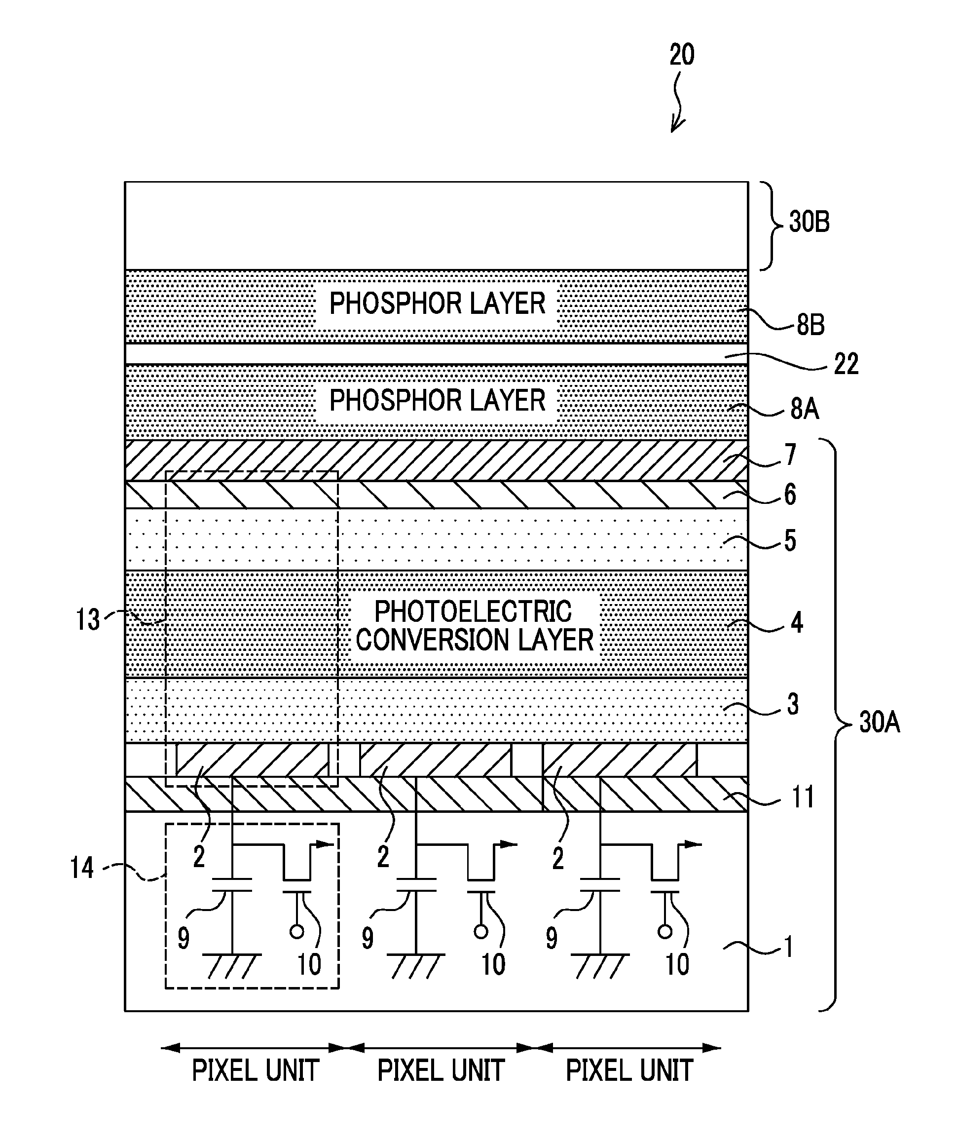
[0058]FIG. 1 is a cross-sectional view showing the schematic configuration of three pixel units of the radiation detector 20 which is an embodiment of the present invention.

[0059]In the radiation detector 20, a TFT substrate 30A obtained by forming a signal output section 14, a sensor section 13, and a transparent insulating layer 7 in this order, a scintillator 8A, a base 22, a scintillator 8B, and a TFT substrate 30B with the same configuration as the TFT substrate 30A are laminated on an insulating substrate 1 in this order from the emission side of radiation. A pixel unit is formed by the signal output sections 14 and the sensor sections 13 of the TFT substrates 30A and 30B. A plurality of pixel units are arrayed on the substrate 1, and each pixel unit is constituted such that the signal output section 14 and the sensor section 13 overlap each...

second embodiment

[0157]Next, a second embodiment will be described.

[0158]First, the configuration of an indirect conversion type radiation detector 20B according to the second embodiment will be described with reference to FIG. 13. Moreover, in FIG. 13, the same components as in the first embodiment are denoted by the same reference numerals as in the first embodiment, and explanation thereof will be omitted.

[0159]As shown in FIG. 13, the radiation detector 20B according to the present embodiment is formed by laminating a base 22A, a reflective layer 12, a scintillator 8A, an adhesive layer 23, a TFT substrate 30A, a base 22B, a scintillator 8B, and a TFT substrate 30B in this order from the opposite side to the emission side of the radiation X.

[0160]Here, the reflective layer 12 reflects visible light. Accordingly, by forming the reflective layer 12, light generated in the scintillators 8A and 8B can be more efficiently guided to the TFT substrate 30A. As a result, the sensitivity is improved. Any ...

third embodiment

[0165]Next, a third embodiment will be described.

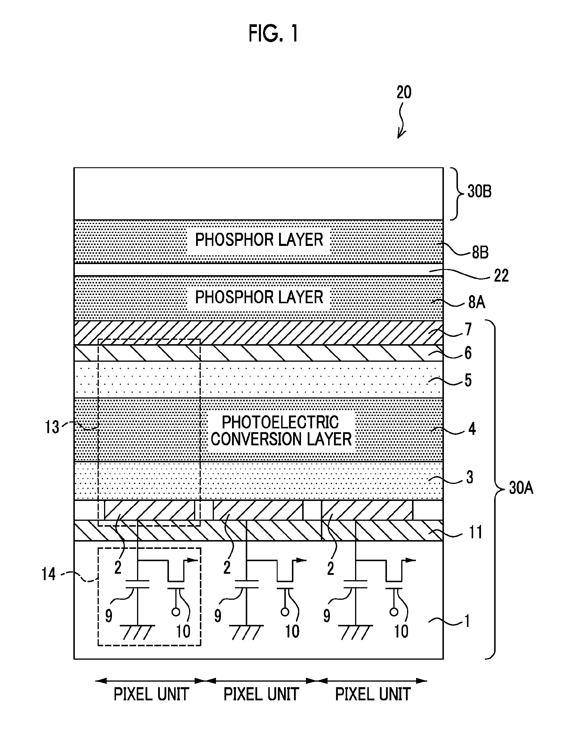
[0166]First, the configuration of an indirect conversion type radiation detector 20C according to the third embodiment will be described with reference to FIG. 14. Moreover, in FIG. 14, the same components as in the second embodiment are denoted by the same reference numerals as in the second embodiment, and explanation thereof will be omitted. In addition, in the same manner as in the first embodiment, it is preferable to perform control such that the distal end of each columnar portion of a scintillator 8A according to the present embodiment is as flat as possible.

[0167]As shown in FIG. 14, the radiation detector 20C according to the present embodiment is formed by laminating a TFT substrate 30A, a scintillator 8A, an adhesive layer 23, a TFT substrate 30B, a scintillator 8B, a reflective layer 12, and a base 22B in this order from the opposite side to the emission side of the radiation X.

[0168]Various methods may be adopted as meth...


PUM


Abstract

There are provided a radiation detector and a radiological image radiographing apparatus capable of improving the quality of an obtained radiological image while suppressing the deterioration of the sensitivity of a phosphor layer according to the cumulative dose of radiation. In the radiation detector, a second scintillator which absorbs lower radiation energy than radiation energy absorbed by a first scintillator and whose deterioration of sensitivity according to the cumulative dose of radiation is larger than that of the first scintillator is provided at the downstream side of the first scintillator in the emission direction of the radiation. In addition, two substrates of a first substrate, which mainly acquires electric charges corresponding to light generated by the first scintillator, and a second substrate, which mainly acquires electric charges corresponding to light generated by the second scintillator, are provided.

Description

BACKGROUND OF THE INVENTION[0001]1. Field of the Invention[0002]The present invention relates to a radiation detector and a radiological image radiographing apparatus. In particular, the present invention relates to a radiation detector which detects an emitted radiation and a radiological image radiographing apparatus which radiographs a radiological image expressed by the radiation detected by the radiation detector.[0003]2. Description of the Related Art[0004]In recent years, a radiation detector such as an FPD (Flat Panel Detector), which has a radiation-sensitive layer disposed on a TFT (Thin Film Transistor) active matrix substrate and which can convert a radiation such as an X-ray directly into digital data, has been put to practical use. A radiological image radiographing apparatus using this radiation detector is advantageous in that an image can be immediately checked and accordingly fluoroscopy (moving image radiographing), which is for radiographing a radiological image ...

Claims


Application Information

Patent Timeline
IPC IPC(8): H01L31/101H01L27/146
CPCA61B6/4216A61B6/4283H01L27/14663H01L27/14661G01T1/2018G01T1/2006
Inventor NISHINO, NAOYUKINAKATSUGAWA, HARUYASUOHTA, YASUNORISATO, KEIICHIRO
Owner FUJIFILM CORP
Why Eureka
Try Eureka