Phosphor incorporated in a thermal conductivity and phase transition heat transfer mechanism

a heat transfer mechanism and thermal conductivity technology, applied in indirect heat exchangers, semiconductor devices of light sources, lighting and heating apparatus, etc., can solve the problems of phosphors degrading rapidly, phosphors to heat, and phosphors that produce desirable output light characteristics degrade quickly, so as to improve the thermal mitigation effect of phosphors

Active Publication Date: 2013-02-28
ABL IP HLDG
View PDF1 Cites 35 Cited by
  • Summary
  • Abstract
  • Description
  • Claims
  • Application Information

AI Technical Summary

Benefits of technology

[0022]In the examples, the thermal cycle of the working fluid within the chamber transfers heat away from some or all of the excited phosphor. This improved heat transfer helps mitigate thermal degradation of the phosphor.

Problems solved by technology

Phosphors tend to degrade over time due to exposure to heat.
However, many applications for phosphor subject the phosphors to heat during device operation.
At least some opto-luminescent phosphors that produce desirable output light characteristics degrade quickly if heated, particularly if heated above a characteristic temperature limit of the phosphor material.
Hence, phosphor thermal degradation can be an issue of concern in many lighting systems.
The lifecycle of the phosphor may also be adversely affected by temperature.
However, the need for more lumens in an output using the phosphor requires larger phosphor unit area, and any limits placed on the flux density to reduce thermal impact on the phosphor constrains the overall device design.
However, there is often a tension or trade off between the size and effectiveness of the heat sink versus the commercially viable size of the device that must incorporate the sink.
For example, if a solid state lamp must conform to the standard form factor of an A-lamp to be a commercially viable product, then that form factor limits the size of the heat sink.
Although these prior technologies do address the thermal issues somewhat, there is still room for further improvement, particularly with regard to thermal issues effecting the phosphor or phosphors in light emitting systems.
Of note, these devices, cooling elements and related thermal mitigation strategies have not been specifically adapted to the cooling of phosphors.

Method used


Image

  • Phosphor incorporated in a thermal conductivity and phase transition heat transfer mechanism
  • Phosphor incorporated in a thermal conductivity and phase transition heat transfer mechanism
  • Phosphor incorporated in a thermal conductivity and phase transition heat transfer mechanism

Examples


Embodiment Construction

[0044]In the following detailed description, numerous specific details are set forth by way of examples in order to provide a thorough understanding of the relevant teachings. However, it should be apparent to those skilled in the art that the present teachings may be practiced without such details. In other instances, well known methods, procedures, components, and / or circuitry have been described at a relatively high-level, without detail, in order to avoid unnecessarily obscuring aspects of the present teachings.

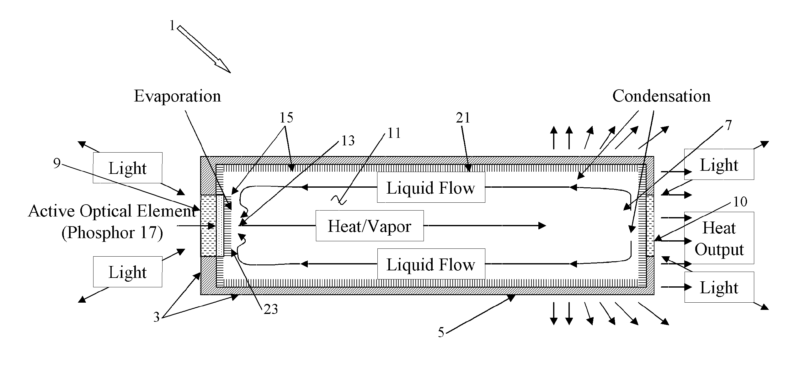
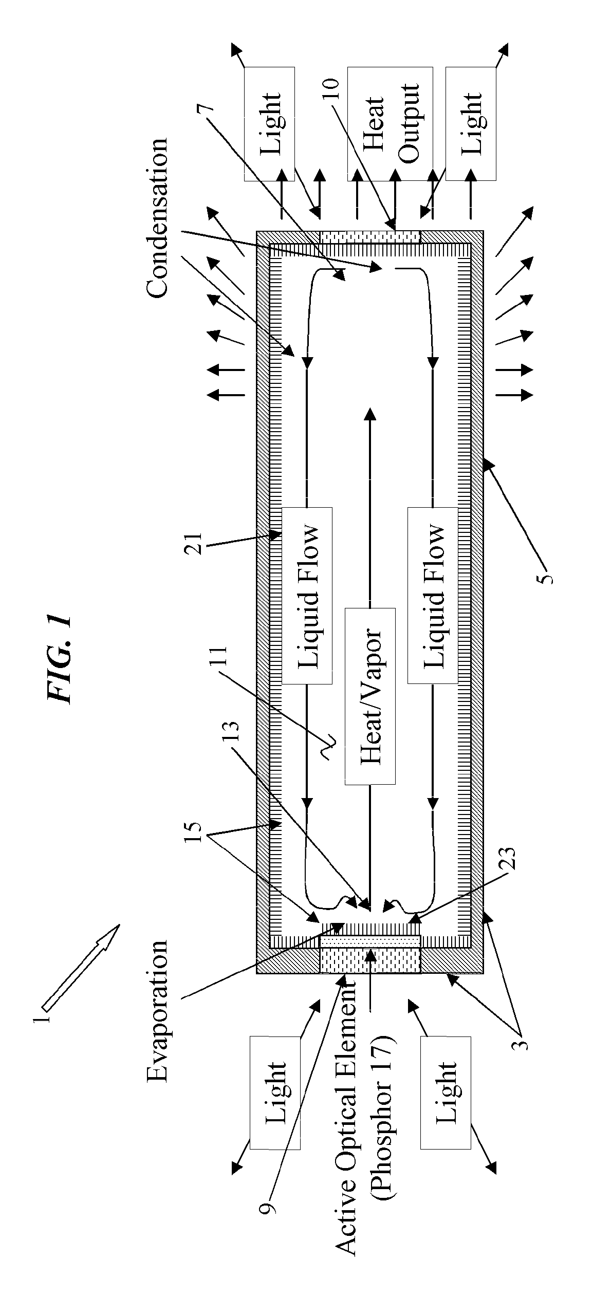
[0045]The various technologies disclosed herein relate to apparatuses, devices or systems for emitting light which utilize a phosphor, where the phosphor is included in the chamber of a cooling element such as a thermal conductivity and phase transition heat transfer mechanism. A variety of examples of such arrangements as well as techniques for making and operating such mechanisms, etc., that so include the phosphor, are discussed below.

[0046]For example, a thermal condu...


PUM


Abstract

A thermal conductivity and phase transition heat transfer mechanism has an opto-luminescent phosphor contained within the vapor chamber of the mechanism. The housing includes a section that is thermally conductive and a member that is at least partially optically transmissive, to allow emission of light produced by excitation of the phosphor. A working fluid also is contained within the chamber. The pressure within the chamber configures the working fluid to absorb heat during operation of the lighting device, to vaporize at a relatively hot location at or near at least a portion of the opto-luminescent phosphor as the working fluid absorbs heat, to transfer heat to and condense at a relatively cold location, and to return as a liquid to the relatively hot location. Also, the working fluid is in direct contact with or contains at least a portion of the opto-luminescent phosphor.

Description

RELATED APPLICATIONS[0001]This application is related to U.S. Utility application Ser. No. 13 / ______ (attorney docket no. 075588-0147) Filed Aug. ______, 2011 entitled “THERMAL CONDUCTIVITY AND PHASE TRANSITION HEAT TRANSFER MECHANISM INCLUDING OPTICAL ELEMENT TO BE COOLED BY HEAT TRANSFER OF THE MECHANISM.”[0002]This application is related to U.S. Utility application Ser. No. 13 / ______ (attorney docket no. 075588-0155) Filed Aug. ______, 2011 entitled “OPTICAL / ELECTRICAL TRANSDUCER USING SEMICONDUCTOR NANOWIRE WICKING STRUCTURE IN A THERMAL CONDUCTIVITY AND PHASE TRANSITION HEAT TRANSFER MECHANISM.”TECHNICAL FIELD[0003]The present subject matter relates to various thermal conductivity and phase transition heat transfer mechanisms that incorporate phosphor materials to be cooled by operation of the mechanisms.BACKGROUND[0004]Many different types of light emitting or generating devices utilize optically luminescent materials or ‘phosphors’ to produce a desired light output. Opto-lumi...

Claims


Application Information

Patent Timeline
Patent Type & Authority Applications(United States)
IPC IPC(8): H01L33/50F28D15/04H01L33/64
CPCH01L33/50F21V29/89F21K9/135F21V3/02H01L33/24F21Y2101/02F21Y2101/025F21Y2105/008F28D15/046F28D2021/0028H01L2924/0002F21V29/006F21V29/77F21V29/506H01L2924/00F21Y2105/00F21K9/232F21Y2115/30F21Y2115/15F21Y2115/10F21V29/507F21V29/51
Inventor RAMER, DAVID P.RAINS, JR., JACK C.
Owner ABL IP HLDG
Why Eureka
Try Eureka