Anode-illuminated radiation detector

a radiation detector and anode technology, applied in the field of anode illumination radiation detectors, can solve problems such as loss or reduction of detector efficiency

Inactive Publication Date: 2013-02-28
GENERAL ELECTRIC CO
View PDF0 Cites 10 Cited by
  • Summary
  • Abstract
  • Description
  • Claims
  • Application Information

AI Technical Summary

Benefits of technology

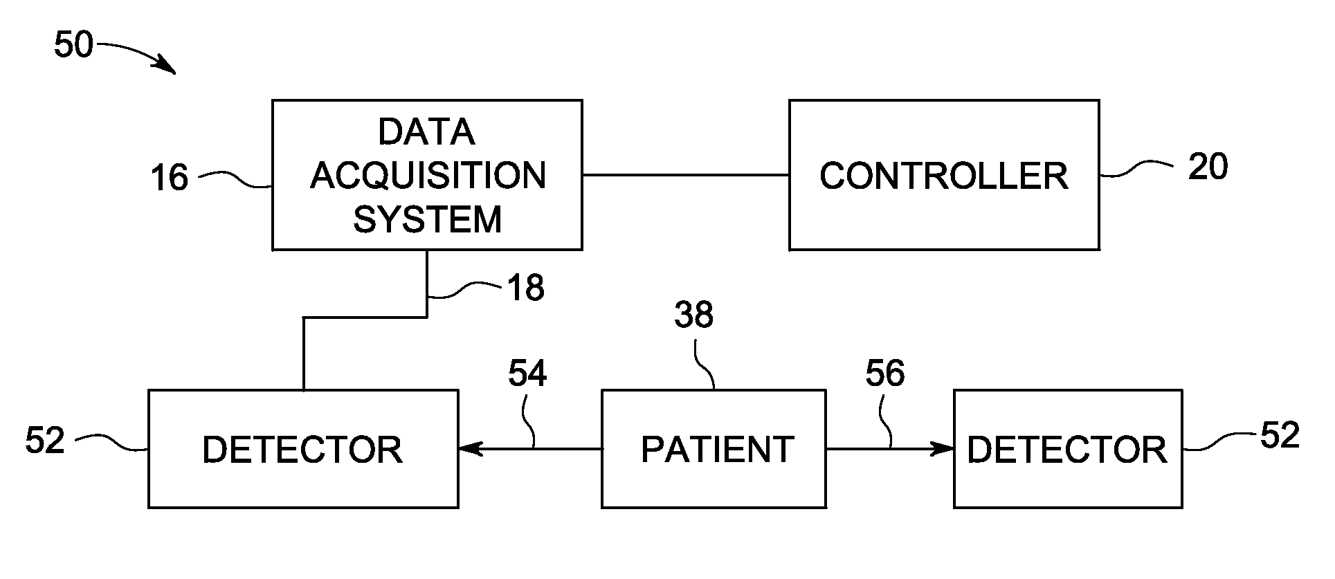
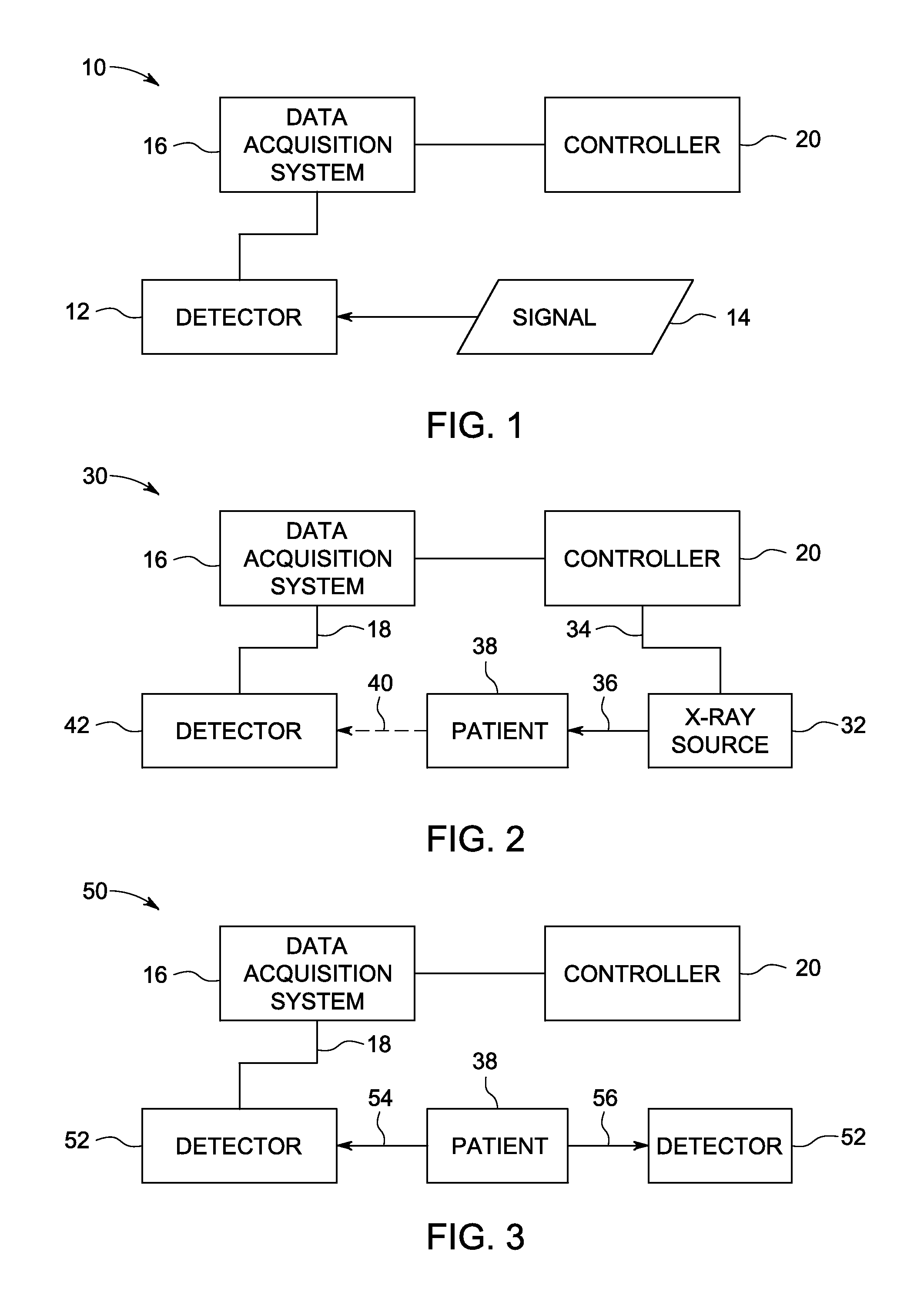
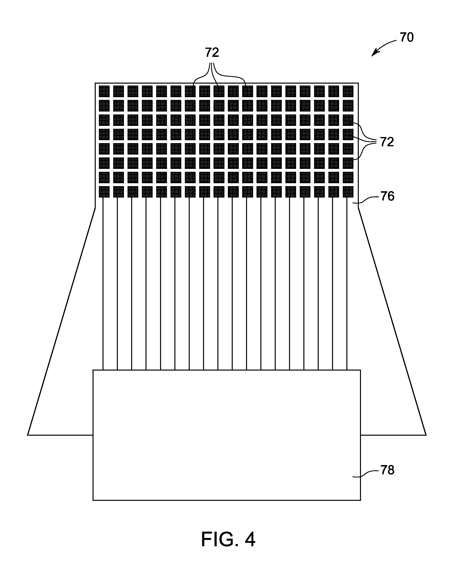
[0004]In accordance with one embodiment, a radiation detector is provided. The radiation detector comprises a plurality of detector elements comprising a direct conversion material that generates electrical signals directly in response to incident radiation. The radiation detector also comprises a respective anode for each detector element. Each anode is positioned over the respective detector element such that incident radiation passes through the anode before reaching the respective detector element. The radiation detector also comprises a flexible circuit structure comprising aluminum or copper interconnect pads in electrical contact with the anodes. The flexible circuit structure comprises one or more layers of a polymeric composition. The radiation detector also compr...

Problems solved by technology

In this manner, radiation signal may be lost to the sensor p...

Method used


Image

  • Anode-illuminated radiation detector
  • Anode-illuminated radiation detector
  • Anode-illuminated radiation detector

Examples


Embodiment Construction

[0021]The present disclosure relates to the use of direct conversion detectors in radiation-based imaging applications. In a direct conversion detector, each radiation photon that is absorbed in the sensor material is converted to a number of electron-hole pairs in proportion to the energy of the radiation photon. A voltage applied across the thickness of the sensor drives the electrons to the anode and the holes to the cathode. Because the mobility of electrons is typically greater than holes in semiconductors with good radiation stopping power, the electron charge is collected on an array of anode electrodes. The electron charge is converted by read-out circuit to a digital imaging signal. The holes are collected on a cathode that is common to the whole sensor area and are not converted to an imaging signal. The anode pixel receiving the electrons is spatially correlated to the arrival position of each photon. Typically, the anode electrode is the pixel-array electrode and the cat...


PUM


Abstract

Interconnect structures suitable for use in connecting anode-illuminated detector modules to downstream circuitry are disclosed. In certain embodiments, the interconnect structures are based on or include low atomic number or polymeric features and/or are formed at a density or thickness so as to minimize or reduce radiation attenuation by the interconnect structures.

Description

BACKGROUND[0001]Non-invasive imaging technologies allow images of the internal structures of a subject (e.g., a patient or object) to be obtained without performing an invasive procedure on the patient or object. Non-invasive imaging systems may operate based on the transmission and detection of radiation through or from a subject of interest (e.g., a patient or article of manufacture). For example, X-ray based imaging techniques (such as mammography, fluoroscopy, computed tomography (CT), and so forth) typically utilize an external source of X-ray radiation that transmits X-rays through a subject and a detector disposed opposite the X-ray source that detects the X-rays transmitted through the subject. Other radiation based imaging approaches, such as positron emission tomography (PET) or single photon emission computed tomography (SPECT) may utilize a radiopharmaceutical that is administered to a patient and which results in the emission of gamma rays from locations within the pati...

Claims


Application Information

Patent Timeline
IPC IPC(8): H01L27/146H01L31/18
CPCH01L27/14636H01L27/14659H01L27/14683H01L27/14618H01L27/14696A61B6/4208A61B6/037H01L27/14676H01L2924/0002H01L2924/00
Inventor LOBASTOV, VLADIMIR A.DUROCHER, KEVIN MATTHEWTKACZYK, JOHN ERICROSE, JAMES WILSONMCCONNELEE, PAUL ALAN
Owner GENERAL ELECTRIC CO
Why Eureka
Try Eureka