Axial flux permanent magnet synchronous generator and motor

a permanent magnet synchronous generator and synchronous generator technology, applied in the direction of magnetic circuits, electrical apparatus, dynamo-electric machines, etc., can solve problems such as degrading output efficiency, and achieve the effects of reducing generation efficiency, improving generation efficiency, and increasing output voltag

Inactive Publication Date: 2013-02-28
IND ACADEMIC COOPERATION FOUND OF KYUNGNAM UNIV
View PDF10 Cites 26 Cited by
  • Summary
  • Abstract
  • Description
  • Claims
  • Application Information

AI Technical Summary

Benefits of technology

[0031]The axial flux permanent magnet synchronous generator for wind turbine generators of the present disclosure has the following advantageous effects.
[0032]Since the generator of the embodiment employs slotted upper and lower stators, it helps to improve the generation efficiency and higher output voltage over conventional axial flux permanent magnet synchronous generators which have been troubled with reduced generation efficiency and output voltage due to low generation voltage under relatively high magnetic resistance in airgap.
[0033]An upper stator twisted with respect to a lower stator by a predetermined electrical angle helps to reduce cogging torque to enable the accompanying wind turbine generator to start with small wind flow.
[0034]The configuration of a rotor fitted with permanent magnets and then adjoined by opposite stators on its top and bottom has the rotor serving as cooling fan to provide advantages in the aspects of generating efficiency and output voltage gain.

Problems solved by technology

Although such coreless stator configuration has the merit of avoiding the cogging torque, greater magnetoresistance in airgaps generates lower voltage, and thereby degrades the output efficiency.

Method used


Image

  • Axial flux permanent magnet synchronous generator and motor
  • Axial flux permanent magnet synchronous generator and motor
  • Axial flux permanent magnet synchronous generator and motor

Examples


Embodiment Construction

[0047]Hereinafter, embodiments of the present disclosure will be described in detail with reference to the accompanying drawings. In the following description, like reference numerals designate like elements although they are shown in different drawings. Further, in the following description of the present embodiments, a detailed description of known functions and configurations incorporated herein will be omitted for the purpose of clarity.

[0048]Detailed descriptions will be provided on an axial flux permanent magnet synchronous generator according to an embodiment, referring to the drawings.

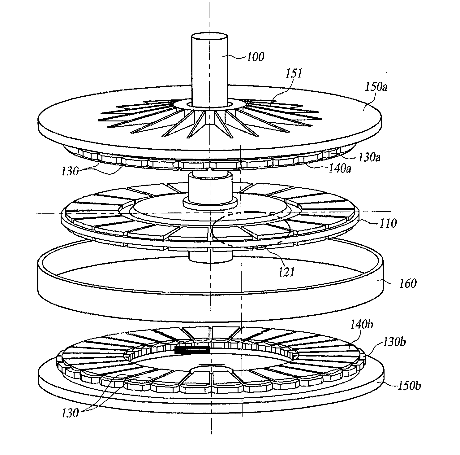
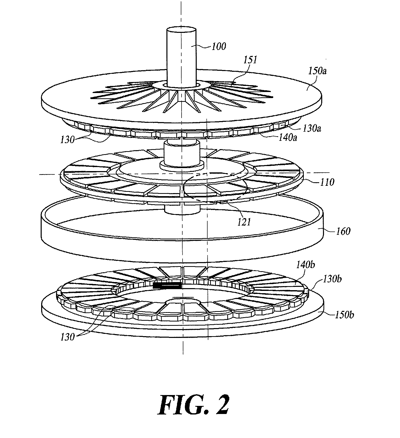
[0049]This embodiment of the AFPM synchronous generator includes a shaft 100, a rotor 110, skewed permanent magnets 122, an upper stator 140a, a lower stator 140b, an upper housing 150a, a lower housing 150b and a hub housing 160.

[0050]First, referring to FIGS. 2, 4 and 7, shaft 100 is a means for receiving a driving force from a driving force generation apparatus of a wind turbine generator. S...


PUM


Abstract

An axial flux synchronous generator for wind turbine generators is provided including a shaft coupled to receive power with a power generating apparatus for the wind turbine; a rotor coupled rotatably to the shaft and having upper and lower disk-like faces affixed with a plurality of skewed permanent magnets having north-south (N-S) pole pairs and distantly arranged; an upper stator and a lower stator both having a plurality of slots formed similar to the skewed permanent magnets for taking windings of a coil, the upper stator being displaced relative to the lower stator by an electric angle in the range of 25˜30°; an upper housing and a lower housing for housing the rotor, the upper stator and the lower stator together; and a hub housing for fastening the upper housing and the lower housing to maintain constant gaps between the rotor and the upper stator and the lower stator.

Description

TECHNICAL FIELD[0001]The present disclosure relates to an axial flux permanent magnet synchronous generator and motor. More particularly, the present disclosure relates to a synchronous generator and motor constructed for effectively reducing cogging torque.BACKGROUND[0002]The statements in this section merely provide background information related to the present disclosure and may not constitute prior art.[0003]Recent technological interests point to a gearless type axial flux permanent magnet synchronous generator to achieve an improved efficiency and power increase of the wind turbine generator.[0004]Moreover, the axial flux permanent magnet synchronous generator may be made into a thin disc shape with magnetic flux for generating the torque extending in the same direction as the axis of the generator. The synchronous generator can operate with high-efficiency relative to other generators since it has shorter magnetic path.[0005]FIG. 1 illustrates a prior art AFPM (axial flux per...

Claims


Application Information

Patent Timeline
Patent Type & Authority Applications(United States)
IPC IPC(8): H02K21/24
CPCH02K21/24H02K2201/06H02K29/03
Inventor JUNG, TAEUK
Owner IND ACADEMIC COOPERATION FOUND OF KYUNGNAM UNIV
Why Eureka
Try Eureka