Imaging system and imaging optical system

a technology of which is applied in the field of imaging optical system and imaging optical system, can solve the problems of deterioration of lens performance and likely decrease of magnification in the edge portion of the lens compared to the center portion,

Active Publication Date: 2013-02-28
RICOH KK
View PDF5 Cites 40 Cited by
  • Summary
  • Abstract
  • Description
  • Claims
  • Application Information

AI Technical Summary

Benefits of technology

[0010]It is, therefore, an object of the present invention to provide a new imaging system capable of imaging an image having a uniform quality over the entire imaging range, and an imaging optical system for use in such an imaging system.
[0011]In order to achieve the above object, one embodiment of the present invention provides an imaging system, including: n or more photographing optical systems having an imaging optical system having a full angle of view A (degree) larger than 360/

Problems solved by technology

However, the thickness of the lens constituting the lens system is reduced, resulting in a deterioration in lens performance.
On the other hand, when co

Method used


Image

  • Imaging system and imaging optical system
  • Imaging system and imaging optical system
  • Imaging system and imaging optical system

Examples


example

[0110]

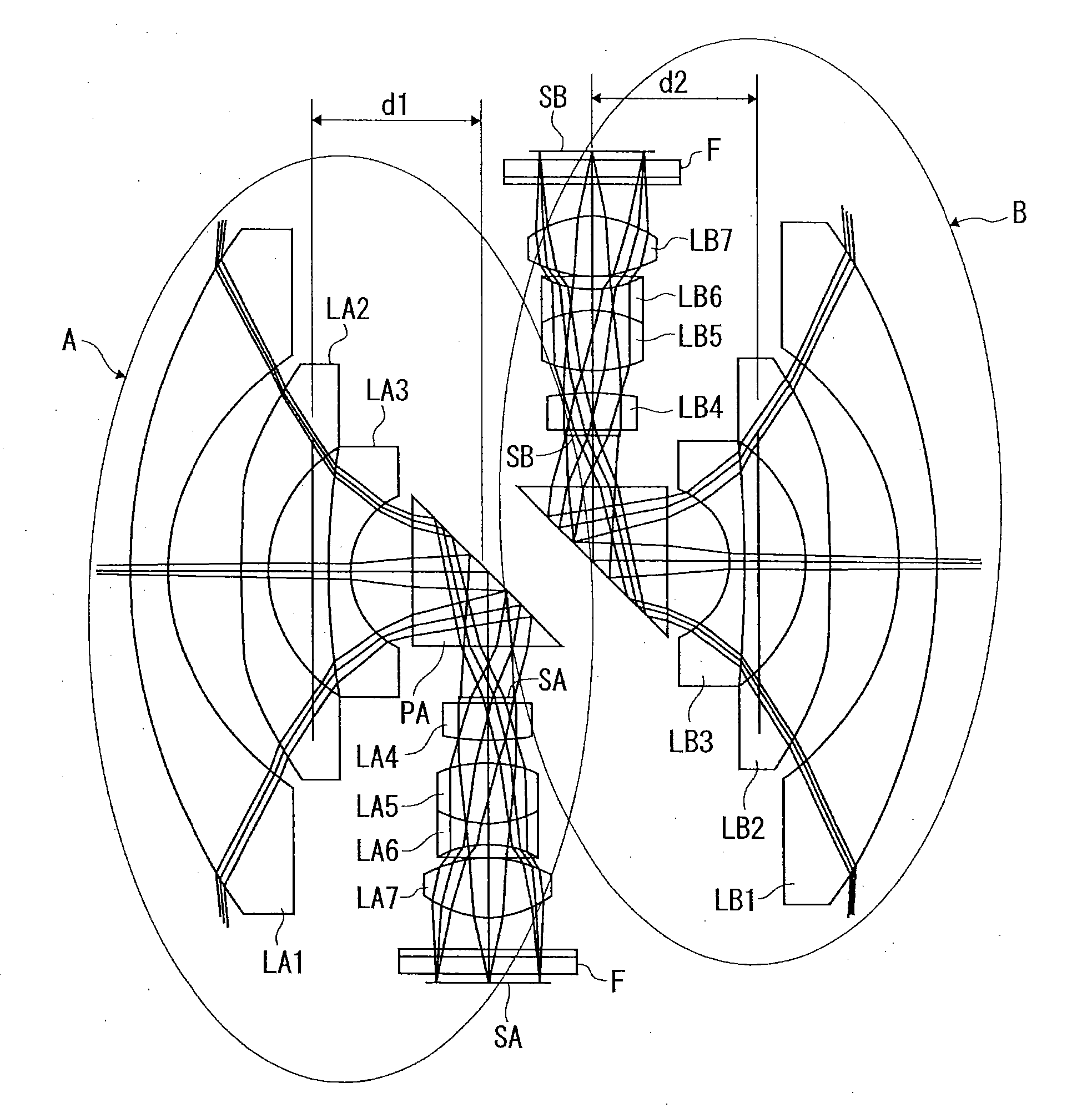
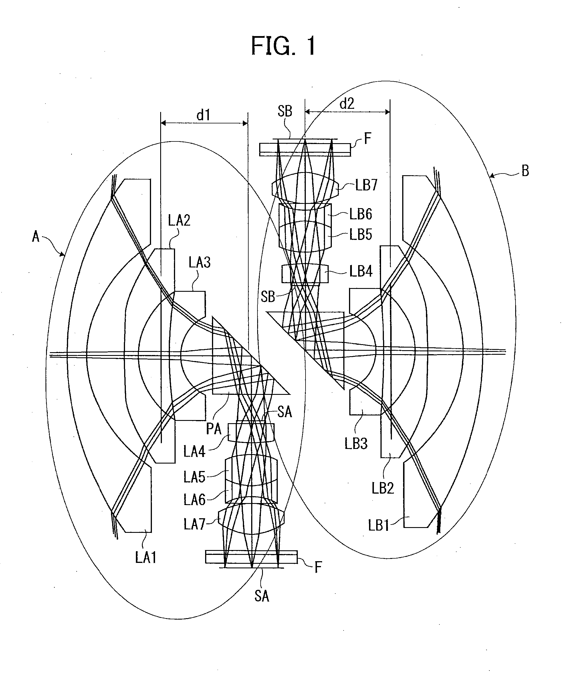
f = 0.75, No = 2.14, ω = 190-degreeSURFACENUMBERRDNdνd 117.11.21.83480742.725324 27.42.27 3−18090.81.53113155.753858 4*4.582 5*17.10.71.63999960.078127 62.51.6 7∞0.3 8∞51.83400037.160487 9∞1.9210∞(APERTURE STOP)0.151193.21.061.92286018.89691212−6.561.0133.371.861.75499852.32143414−30.71.92286018.8969121530.3 16*2.71.971.53113155.753858 17*−2.190.818∞0.41.51633064.14202219∞020∞0.31.51633064.14202221∞0.322IMAGING SURFACE

[0111]Aspheric Surface

[0112]Surfaces having * (both surfaces of second lens in front group and both surfaces of final lens in back group) in the above data are aspheric surfaces.

[0113]An aspheric surface shape is expressed by the following known equation by using an inverse of a paraxial curvature radius (paraxial curvature) C, a height from an optical axis H, a conical constant K, and an aspheric surface coefficient of each order with X as the aspheric surface amount in the optical axis direction, and is defined by providing the paraxial curvature radius, conica...


PUM


Abstract

An imaging system includes n or more photographing optical system having an imaging optical system having a full angle of view A (degree) larger than 360/n where n is a natural number of 2 or more and a two-dimensional imaging element configured to convert light condensed by the imaging optical system into an image signal, wherein in the imaging optical system of each of the imaging optical systems, a magnification per unit angle of view monotonically increases from 0 to 360/n-degree angle of view, and an increase rate of the magnification monotonically decreases to the full angle of view A (degree) after the 360/n-degree angle of view.

Description

PRIORITY CLAIM[0001]The present application is based on and claims priority from Japanese Patent Application No. 2011-185217, filed on Aug. 26, 2011, the disclosure of which is hereby incorporated by reference in its entirety.BACKGROUND[0002]1. Field of the Invention[0003]The present invention relates to an imaging system and an imaging optical system for use in the imaging system.[0004]2. Description of the Related Art[0005]As an imaging system which images all directions at one time, an imaging system having a plurality of wide-angle lenses is known. Unlike an imaging lens for normal plane photographing, a wide-angle lens for use in such an imaging system often includes different magnification between the center thereof and the edge portion thereof.[0006]As such, it is necessary to increase the imaging magnification in the edge portion of the lens so as to be higher than that in the center of the lens in order to compensate image quality deterioration in the edge portion of the le...

Claims


Application Information

Patent Timeline
IPC IPC(8): H04N5/225
CPCG02B13/06H04N5/2258H04N5/23238G02B5/04H04N23/45H04N23/55H04N23/698G03B37/04
Inventor MASUDA, KENSUKETERAO, NORIYUKIIRINO, YOSHIAKITANAKA, TOMONORIIMAE, NOZOMIHARADA, TORUTAKENAKA, HIROKAZUYAMAMOTO, HIDEAKISAWAGUCHI, SATOSHISATOH, HIROYUKI
Owner RICOH KK
Why Eureka
Try Eureka